
Stabilizing device for full-automatic traveling crane component

A stabilizing device, fully automatic technology, applied in hoisting device, load block, traveling mechanism, etc., can solve the problems of staff injury, electric hoist imbalance, breakage, etc., to prevent personal injury, ensure stability, and reduce the possibility Effect

Active Publication Date: 2022-01-28
STATE GRID HEBEI ELECTRIC POWER CO LTD +2
View PDF16 Cites 1 Cited by
  • Summary
  • Abstract
  • Description
  • Claims
  • Application Information

AI Technical Summary

Problems solved by technology

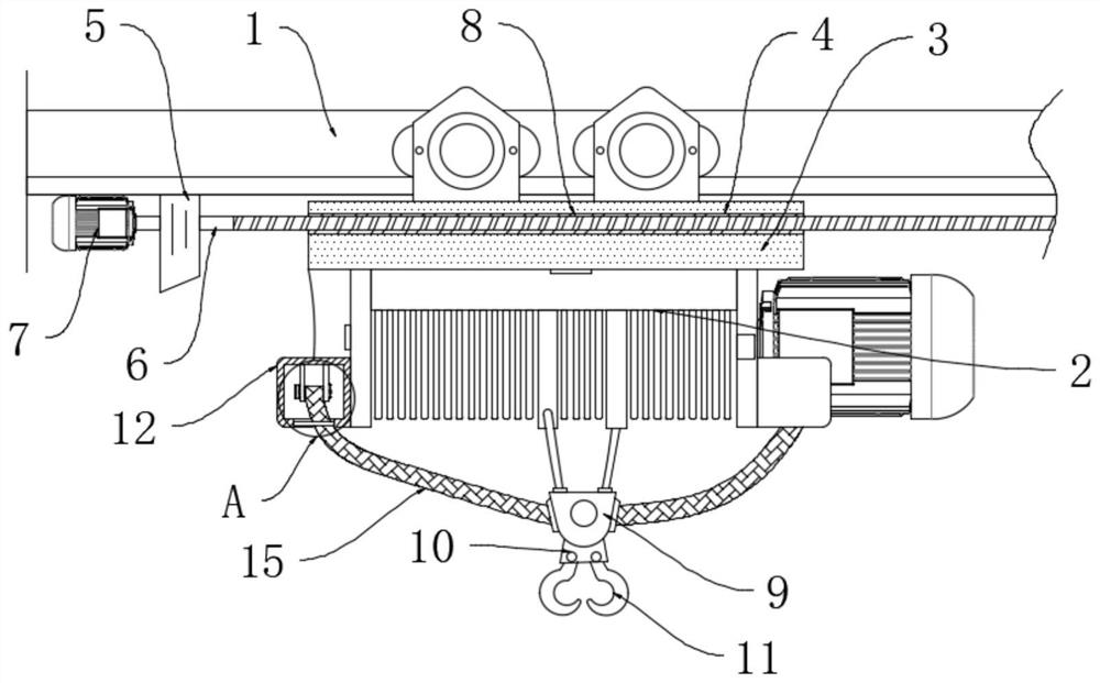
[0002] Crane is a common name for cranes, cranes, cranes and other cranes. It is often used in workshops, docks, construction sites, etc. It can lift and move heavy objects. It is one of the important machinery in logistics transportation. Light and small cranes The main moving component is the electric hoist, including the lifting mechanism and the moving mechanism, and the heavy objects are mainly moved through the hook. However, during the use of the existing light and small cranes, most of them are single-hook structures, and the stability of the heavy objects is relatively high. It is easy to cause the shaking of the steel cable, which may lead to the unbalance of the electric hoist. After long-term use, there will be a gap between the moving mechanism of the electric hoist and the guide rail, and there are certain safety hazards in the unstable movement of heavy objects. Injuries may be caused, and may also cause wear and tear on the steel cables, and heavy objects may fall. In view of this, we propose a stabilizing device for fully automatic driving components

Method used


Image

  • Stabilizing device for full-automatic traveling crane component
  • Stabilizing device for full-automatic traveling crane component
  • Stabilizing device for full-automatic traveling crane component

Examples


Embodiment Construction

[0021] The following will clearly and completely describe the technical solutions in the embodiments of the application with reference to the drawings in the embodiments of the application. Apparently, the described embodiments are only some of the embodiments of the application, not all of them. The following description of at least one exemplary embodiment is merely illustrative in nature and in no way serves as any limitation of the application, its application or uses. Based on the embodiments in this application, all other embodiments obtained by persons of ordinary skill in the art without creative efforts fall within the protection scope of this application.

[0022] It should be noted that the terminology used here is only for describing specific implementations, and is not intended to limit the exemplary implementations according to the present application. As used herein, unless the context clearly dictates otherwise, the singular is intended to include the plural, a...


PUM


Abstract

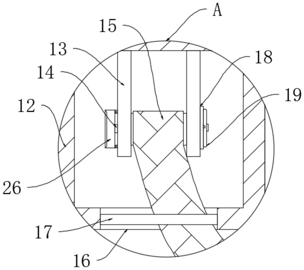
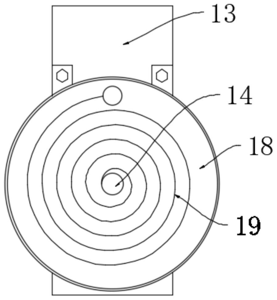
The invention relates to the technical field of logistics machinery, in particular to a stabilizing device for a full-automatic travelling crane component, which comprises a guide rail and an electric hoist, a stabilizing frame is fixedly mounted on the electric hoist, a threaded groove is formed in the stabilizing frame, a bearing seat is fixedly mounted on the guide rail, a screw is rotatably mounted on the bearing seat, the screw is driven by a motor, a reserved gap is formed between the screw and the groove wall of the threaded groove, a lifting appliance is connected to the electric hoist, and lifting hooks are installed on the lifting appliance through a rotating shaft; the two lifting hooks are used for lifting a heavy object, the anti-falling belts are connected to the two sides of the lifting appliance, when the heavy object normally descends, the anti-falling belts are slowly pulled to drive the belt shaft to rotate, a locking structure cannot be triggered, a belt shaft can rotate a volute spiral spring from the middle, potential energy is accumulated in the volute spiral spring, the resistance generated by the volute spiral spring acts on the two sides of the lifting appliance, so that the stability of the lifting appliance is guaranteed, and the lifting appliance is prevented from shaking.

Description

technical field [0001] The invention relates to the technical field of logistics machinery, in particular to a stabilizing device for fully automatic driving components. Background technique [0002] Crane is a common name for cranes, cranes, cranes and other cranes. It is often used in workshops, docks, construction sites, etc. It can lift and move heavy objects. It is one of the important machinery in logistics transportation. Light and small cranes The main moving component is the electric hoist, including the lifting mechanism and the moving mechanism, and the heavy objects are mainly moved through the hook. However, during the use of the existing light and small cranes, most of them are single-hook structures, and the stability of the heavy objects is relatively high. It is easy to cause the shaking of the steel cable, which may lead to the unbalance of the electric hoist. After long-term use, there will be a gap between the moving mechanism of the electric hoist and th...

Claims


Application Information

Patent Timeline
Patent Type & Authority Applications(China)
IPC IPC(8): B66C11/00B66C9/14B66D1/12B66D1/30B66C1/34B66C13/06
CPCB66C11/00B66C9/14B66D1/12B66D1/30B66C1/34B66C13/06
Inventor 李科锋王增超苏明郝锋张忆南赵宇琦田诚付艳阳
Owner STATE GRID HEBEI ELECTRIC POWER CO LTD
Learn More