Assembled large-span temporary supporting structure
A temporary support and large-span technology, which is applied to the preparation of pillars, building structures, and building components on site, can solve the problems of low positioning accuracy of support points and inability to adjust temporary support structures, and shorten the construction period and reduce construction costs. The effect of high workload and high reuse rate
- Summary
- Abstract
- Description
- Claims
- Application Information
AI Technical Summary
Problems solved by technology
Method used
Image
Examples
Embodiment 1
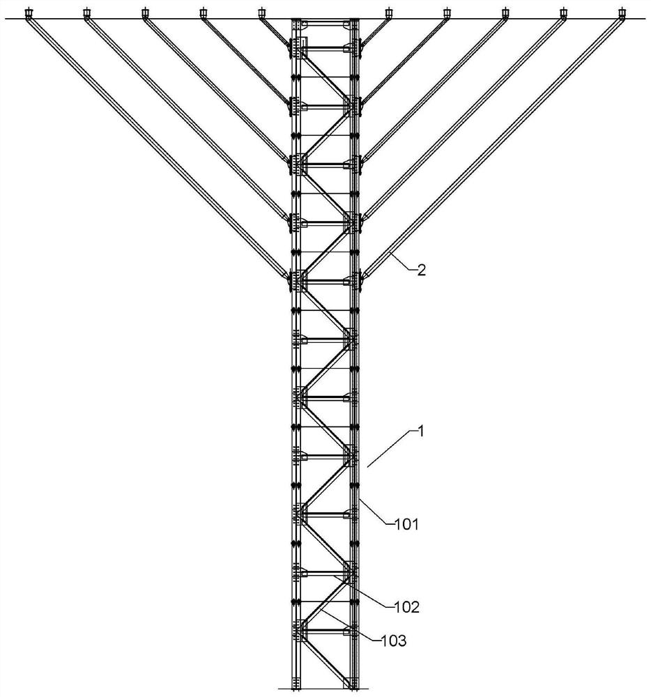
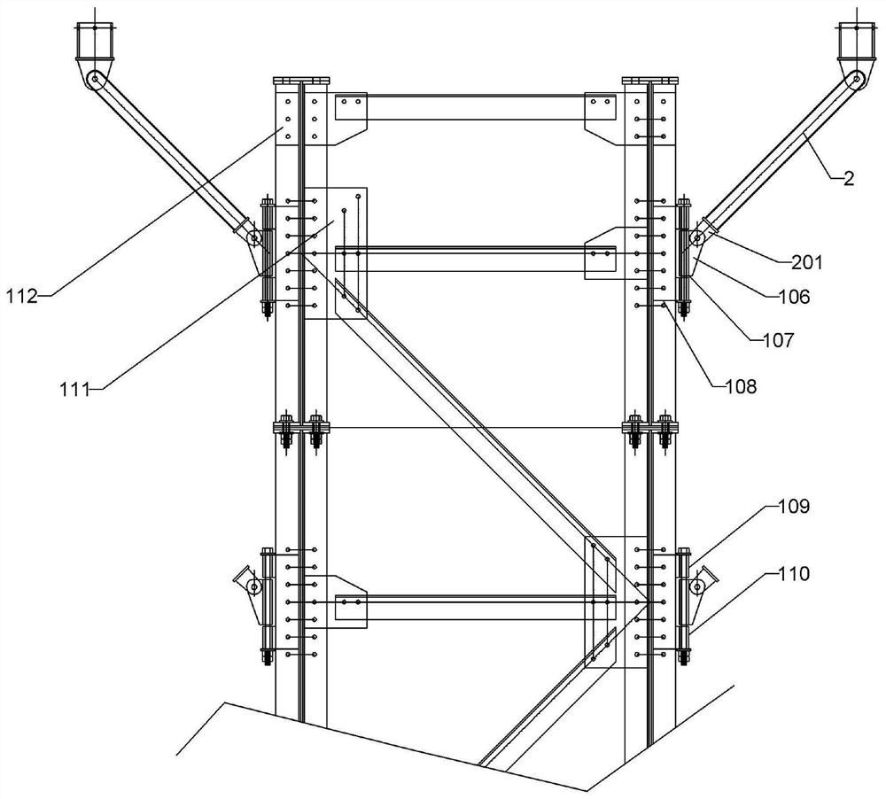
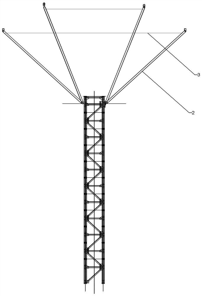
[0030] Append figure 1 , The assembly of large span temporary support structure, comprising a frame 1 and the inclined grid mounted on supporting lattice frame 2, the frame 1 comprises a lattice structure and a plurality of identical standard section connected end to end, each section includes four standard a lattice column 101, four in a square lattice arrangement of columns 101, each column 101 by four lattice side angle 104 is encircled, each edge angle 104 and the other side of the equal angle side back to back, such as attachment Figure 5As shown, the negative bolt 105 is used under the bottom layer of the standard fertilizer, which is embedded in the foundation, and is used for fixing the grid column 101. The adjacent two struts 101 are connected between the bells, including the hydraulic strip 102 and the linked strip 103, the zicodal strip 103 axis and vertical angle of 45 degrees.
[0031] The end plates are provided with an end plate at each equipped angle steel, and the...
Embodiment 2
[0039] In this embodiment, in the present embodiment, in the present embodiment, a laser emitter is provided at a balanced steel loser for each ramp, and a laser emitter is provided at the connection of the balance steel cable and the outermost side. At the connection of the balance steel cable and adjacent oblique support, there is a laser receiver at the steel loser sleeve, and can be used to measure the balance steel cable with the mating of the laser transmitter and the laser receiver. The distance between the outermost oblique support to the balance steel cable cable and the adjacent oblique supporting connection.
[0040] Based on the position of the respective support points calculated, the mounting position on the grid frame can determine the mounting angle of the respective ramp, in theory, each ramp on the grid frame is parallel to each other, each oblique The horizontal distance between the support has been calculated in advance, there is a standard value, but during th...
Embodiment 3
[0042] The present embodiment differs from the examples in that this embodiment, the balance steel cable is a telescopic structure, and three sections are divided into the first segment, the steel lasso sleeve and the second segment, first The ends of the segment and the second segment are inserted within the steel lasso sleeve, and a number of first threaded holes are disposed on the first segment and the second segment, and the second is set in both ends of the steel looting sleeve. Threaded holes, the steel cable tube is fixed to the first and second segments by a positioning bolt in the first threaded hole and the second threaded hole by a thread.
[0043] As the construction progress is different, when the position of the support point changes, the ramp will also adjust. After this design structure, after the various ramp positions change, there is no need to replace the new balance steel race, only need The positioning bolts are adjusted within different first threaded holes...
PUM
 Abstract
Description
Claims
Application Information
 - R&D
- Intellectual Property
- Life Sciences
- Materials
- Tech Scout
- Unparalleled Data Quality
- Higher Quality Content
- 60% Fewer Hallucinations
Browse by: Latest US Patents, China's latest patents, Technical Efficacy Thesaurus, Application Domain, Technology Topic, Popular Technical Reports.
© 2025 PatSnap. All rights reserved.Legal|Privacy policy|Modern Slavery Act Transparency Statement|Sitemap|About US| Contact US: help@patsnap.com


