

Building fire fighting dense smoke rapid exhaust device
An exhaust device and fire-fighting technology, applied in ventilation systems, space heating and ventilation, space heating and ventilation details, etc., can solve problems such as inconvenient treatment of dense smoke, air pollution by harmful substances, inconvenient filter plate anti-blocking, etc. , to achieve the effect of being convenient for full treatment, avoiding air pollution, and avoiding pollution
- Summary
- Abstract
- Description
- Claims
- Application Information
AI Technical Summary
Problems solved by technology
Method used
Image

Examples
Embodiment 1
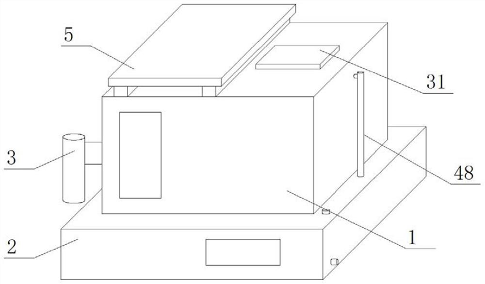
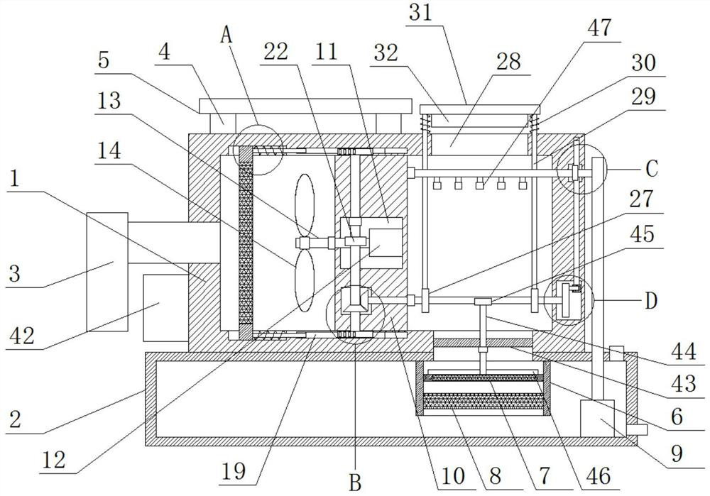
[0022] refer to Figure 1-7, a building fire-fighting dense smoke quick exhaust device, comprising a housing 1, one side of the housing 1 is provided with an installation port, the installation port is fixedly installed with an exhaust pipe 3 by welding, and the bottom of the housing 1 is fixedly installed by welding Water tank 2, the top of the housing 1 is fixed with two symmetrical support plates 4 by welding, the top of the two support plates 4 is fixed with the same solar chip 5 by bolts, and the top of the housing 1 is provided with an air outlet 28 And the water outlet, the water outlet communicates with the water tank 2, the fixed rod 43 is fixedly installed in the water outlet by welding, the top and one side of the water tank 2 are respectively provided with a water inlet and a water discharge port, and the top inner wall of the water tank 2 is fixedly installed with a mounting frame by welding 6. The first filter plate 7 and the activated carbon filter layer 8 are i...
Embodiment 2
[0034] The difference from Embodiment 1 is that a battery 42 is fixedly installed on one side of the housing 1 through bolts, and the solar chip 5 is connected to the battery 42 and the motor 12. The solar chip 5 can convert light energy into electrical energy and store it to In the storage battery 42, the storage battery 42 can be used as an emergency power supply for the motor 12. A protective cover is installed on one side of the casing 1 through bolts, and the storage battery 12 is located in the protective cover. The top of the casing 1 is fixed with two symmetrical As for the connection plate, the tops of the two connection plates are fixedly connected with the same baffle plate by bolts, and the cover plate 31 is located under the baffle plate.
[0035]Working principle, when in use, the exhaust pipe 3 can be connected to the exhaust outlets of each floor, when a fire occurs, the motor 12 and the water pump 9 are turned on, the motor 12 drives the first worm 13 to rotate...
PUM
 Abstract
Description
Claims
Application Information