Bridge vertical displacement real-time monitoring device and method based on fiber grating displacement meter
A fiber grating, vertical displacement technology, applied in measuring devices, optical devices, instruments, etc., can solve the problems of low safety factor, high cost, difficult measurement, etc., and achieve the effects of low cost, improved accuracy, and convenient use.
- Summary
- Abstract
- Description
- Claims
- Application Information
AI Technical Summary
Problems solved by technology
Method used
Image


Examples
Embodiment Construction
[0043] The present invention will be further described below in conjunction with the accompanying drawings and specific embodiments, so that those skilled in the art can better understand the present invention and implement it, but the examples given are not intended to limit the present invention.
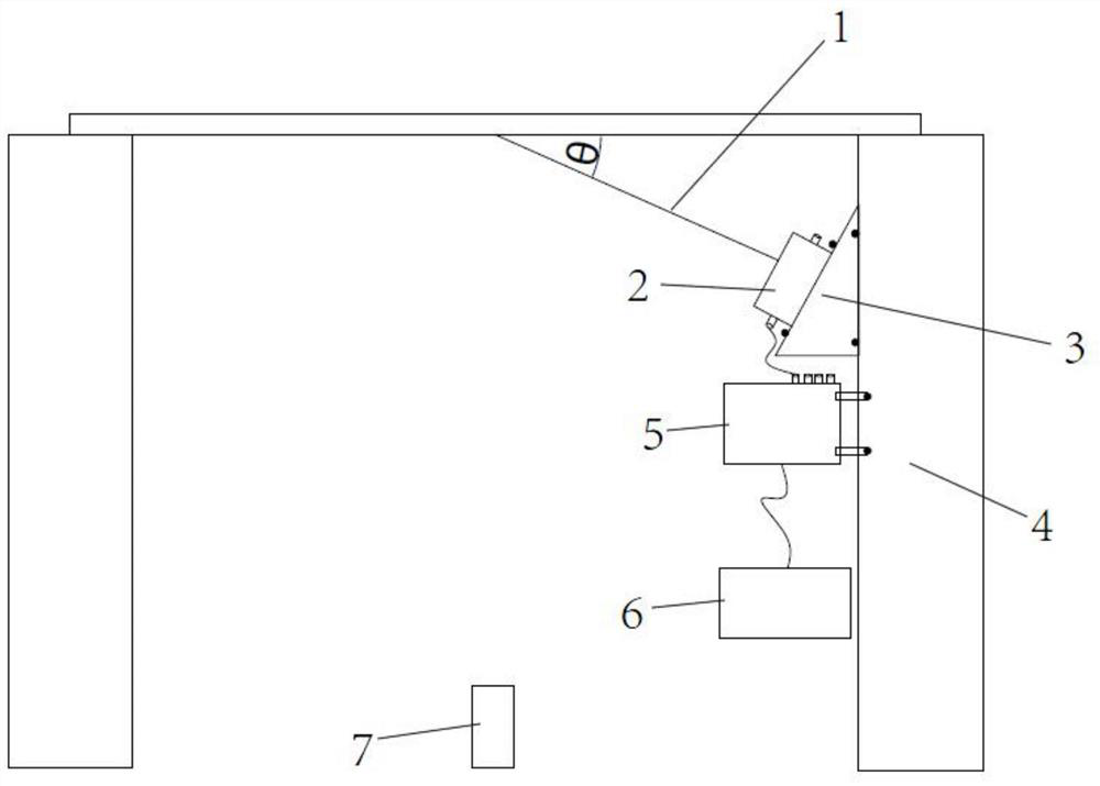
[0044] refer to figure 1 As shown, an embodiment of the bridge vertical displacement real-time monitoring device based on the fiber grating displacement meter of the present invention includes a backguy 1 and a fiber grating displacement meter 2, one end of the backguy is fixed on the measuring point A at the bottom of the bridge, and the other end of the backguy is connected to The detection end of the fiber grating displacement meter is fixed, the fiber grating displacement meter is installed on the angle block 3, the angle block is fixed on the vertical support part 4 of the bridge, and the fiber grating displacement meter is connected to the fiber grating demodulator 5 through ...
PUM
 Abstract
Description
Claims
Application Information
 - Generate Ideas
- Intellectual Property
- Life Sciences
- Materials
- Tech Scout
- Unparalleled Data Quality
- Higher Quality Content
- 60% Fewer Hallucinations
Browse by: Latest US Patents, China's latest patents, Technical Efficacy Thesaurus, Application Domain, Technology Topic, Popular Technical Reports.
© 2025 PatSnap. All rights reserved.Legal|Privacy policy|Modern Slavery Act Transparency Statement|Sitemap|About US| Contact US: help@patsnap.com