Tube seam type anchor rod drawing instrument and drawing method thereof

A tube-seam type, drawing instrument technology, applied in instruments, scientific instruments, measuring devices, etc., to save time, improve detection rate, and reduce the consumption of anchors

Active Publication Date: 2022-01-28
KUNMING UNIV OF SCI & TECH
View PDF11 Cites 0 Cited by
  • Summary
  • Abstract
  • Description
  • Claims
  • Application Information

AI Technical Summary

Problems solved by technology

[0004] In order to make the detection of seam anchors more targeted, the present invention can match seam anchors of different diameters, reduce the cumbersome steps of installing and disassembling components, and thus It is more convenient to use, and reduces the experimental error caused by the wear and tear of the anchor ring and anchor during the long-term disassembly process. A pipe-slit anchor rod puller and its pulling method are proposed. The invention makes the tension axis The grab

Method used


Image

  • Tube seam type anchor rod drawing instrument and drawing method thereof
  • Tube seam type anchor rod drawing instrument and drawing method thereof
  • Tube seam type anchor rod drawing instrument and drawing method thereof

Examples


Example Embodiment

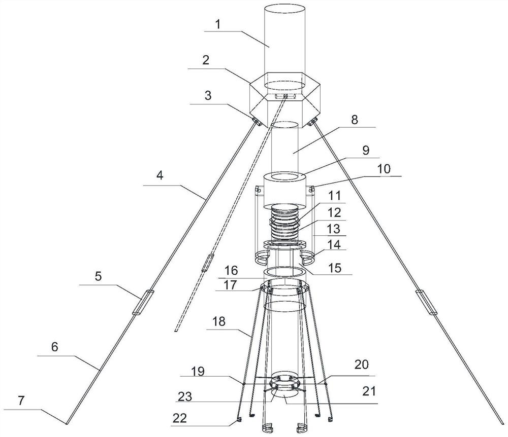
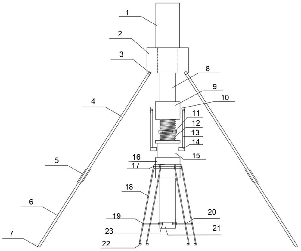
[0038] Example 1: Such as figure 1 , 2 And as shown, a tubular joints anchor drawing instrument 11, including the jack 1, the support member, the spindle 8, the load-bearing seat 9, the slide base 16, tension shaft 18, support shaft 20, base 21 and top grip ring 22 ,

[0039] 1 is fixed at the top of the jack holder member fixed to the bottom end of the jack 1 provided coaxially with a main shaft 8, the load-bearing seat 9 is sleeved on the spindle 8; jack 1, the spindle 8 and the bearing seat 9 is formed bolt drawing strength member ;

[0040]The slide base 16 is sleeved on the spindle 8 and the sliding shoe 16 is located below the load-bearing seat 9, the load-bearing force of bearing seat 9 through the rod 13 is connected to the sliding seat 16;

[0041] Lateral slider 16 by the rotation of the seat base 17 is provided with a tension shaft 18, grip ring 22 is fixed at the bottom end of the tension shaft 18; 21 fixed to the top seat 8 provided on the bottom end of the spindle, t...

Example Embodiment

[0049] Example 2: This example tubular pipe joints slotted bolt drawing instrument is substantially the same as in Example bolt drawing instrument 1, except that: a base support member includes a bracket 2, the major axis leg 4, the lock tightening the ferrule 5, and a minor axis leg 6 7 toes, feet long axis of the top tube 4 via a shaft 3 provided at a bottom end of the rack base 2, the top of the minor axis of the leg 6 is provided in the longitudinal leg jacket tube 4 the bottom end, the locking ferrule sleeve 5 provided in the longitudinal leg of the stub 4 is connected with the legs 6, 7 is fixed toe minor axis disposed at the bottom end of the leg 6;

[0050] When loosening the locking ferrule 5, 6 can be pulled out minor axis leg; when locking the locking ferrule 5, the minor axis can be fixed so as not moving legs 6; 8 and spindle support member to ensure that the test pipe joints exposed anchor rod direction along the same line, i.e., pipe joints to ensure that the pullin...

Example Embodiment

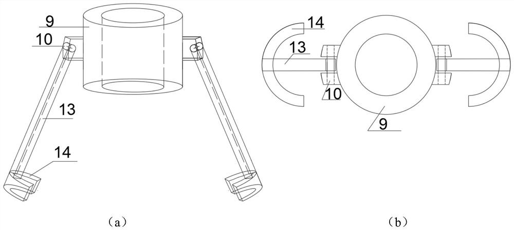
[0051] Example 3: Example pipe joints bolt drawing instrument according to the present embodiment and Example pipe joints bolt drawing instrument 2 embodiment is substantially the same, except that: The Figure 3 ~ 10 FIG, 8 is provided with a central threaded spindle 12, provided with a matching thread 12 on the nut 11, the load-bearing holder 9 is located above the thread 12 of the nut 11, the slide base 16 is positioned under the nut 11, the load-bearing seat and a sliding base 9 8 can slide along the spindle 16, the outer side wall of the load-bearing holder 9 is provided with a projection 10, 10 of the convex body defines a central recess, the recess is provided with a horizontal shaft II, to the top of the bearing force of the lever 13 defines a horizontal through II hole, a horizontal shaft II II through the horizontal through-hole, the load-bearing lever 13 has a bottom end fixed to the collar 14, the top of the slide base 16 defines a slot 15, the collar 14 is provided in ...


PUM


Abstract

The invention relates to a tube seam type anchor rod drawing instrument and a drawing method thereof, and belongs to the technical field of mineral engineering. The tube seam type anchor rod drawing instrument comprises a jack, a support component, a main shaft, a force bearing base, a sliding base, a tension shaft, a supporting shaft, a top base and a grabbing ring, the jack is fixedly arranged at the top end of the support component, the main shaft is coaxially and fixedly arranged at the bottom end of the jack, and the force bearing base is arranged on the main shaft in a sleeving mode; the jack, the main shaft and the force bearing base form an anchor rod drawing component; the sliding base is arranged on the main shaft in a sleeving mode and located below the force bearing base, and the force bearing base is connected with the sliding base through the force bearing rod. The tension shaft is arranged on the side face of the sliding base through a rotating base. The grabbing ring is fixedly arranged at the bottom end of the tension shaft. The top base is fixedly arranged at the bottom end of the main shaft, the A end of the supporting shaft is arranged on the side face of the top base, and the B end of the supporting shaft is hinged to the tension shaft. The grabbing ring at the end of the tension shaft gets close to or away from the center line of the main shaft by moving the sliding base so that the tube seam type anchor rods with different diameters are matched in the test.

Description

technical field [0001] The invention relates to a pipe slit type bolt puller, which belongs to the field of mining engineering. Background technique [0002] Anchor puller is used to test the pull-out resistance of various anchors, steel bars and other anchors. It is a necessary testing instrument for quality inspection units. The commonly used bolt puller is composed of manual pump, hydraulic cylinder, intelligent digital display pressure gauge, reaction support ring, anchorage and so on. When using, first select the corresponding anchor, install the reaction support ring, oil cylinder, and anchor in sequence, then connect the manual pump, pressurize the hydraulic cylinder through the manual pump, and read the pressure gauge to check the pullout force of the anchor. Determination, after dismantling the instrument, if there is no crack or other local damage in the concrete, it should be evaluated as qualified. The pipe slot bolt is a new type of full-length anchor that act...

Claims


Application Information

Patent Timeline
IPC IPC(8): G01N3/02G01N3/04G01N3/08
CPCG01N3/02G01N3/04G01N3/08
Inventor 孙伟姜明归张盛友李金鑫卢开放高通赵建光李兆宇樊锴刘增
Owner KUNMING UNIV OF SCI & TECH
Why Eureka
Try Eureka