Eureka AIR delivers breakthrough ideas for toughest innovation challenges, trusted by R&D personnel around the world.

Detection system for analyzing one or more particles

A detection system and particle technology, which is used in the analysis of materials, material excitation analysis, material analysis by optical means, etc., can solve the problems of complex sample suction process, affecting the accuracy of detection results, cleaning sample probes, etc.

Pending Publication Date: 2022-01-28
深圳市液芯科技有限公司
View PDF1 Cites 0 Cited by
  • Summary
  • Abstract
  • Description
  • Claims
  • Application Information

AI Technical Summary

Problems solved by technology

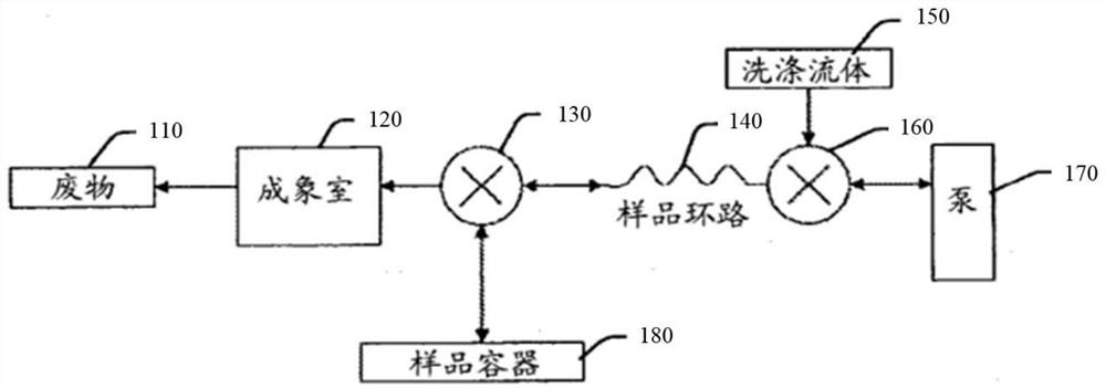
In the preferred form of this patent, as figure 1 As shown, its fluid processing subsystem includes a sample container 180, a sample loop 140, an imaging chamber 120, two valves (130 and 160) and a pump 170, etc., which require the sample loop 140 to temporarily store samples, and the sample loop 140 The existence of the pipe will lengthen the pipe required to drive the sample to the imaging chamber, and the sample suction process will become complicated, and because the particles to be analyzed will partially remain on the pipe wall or in the pipe during the process of driving the sample into the imaging chamber, it is relatively difficult A long pipeline will increase the loss of particles, which will affect the accuracy of the detection results
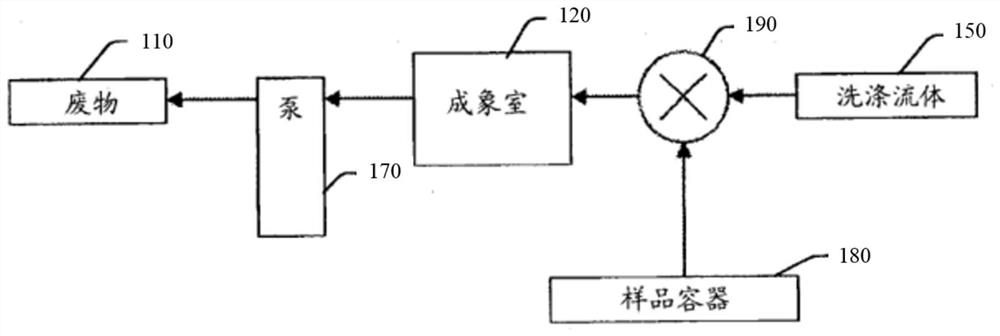
The patent also provides an alternative liquid circuit, such as figure 2 As shown, it does not have the sample loop 140 to save costs, but it cannot clean the sample probe with washing fluid, resulting in that after one sample is detected, when the next sample is detected, the previous sample remains in the sample probe, interfere with the test results

Method used


Image

  • Detection system for analyzing one or more particles
  • Detection system for analyzing one or more particles
  • Detection system for analyzing one or more particles

Examples


Embodiment 1

[0099] Embodiment one ( Image 6The embodiment of the liquid circuit subsystem shown), in this embodiment, in Figure 5 On the basis of the shown liquid circuit subsystem, the liquid circuit subsystem is added with a first gating device 34 . In this embodiment, the first gating device 34 has an outlet 1 , an inlet 2 and a liquid outlet 3 . The first gating device 34 gates the detection chamber 33, the sampling needle a and the drain port 3, specifically, it is used to connect the outlet 1 with the inlet 2 after switching; and connect the outlet 1 to the drain port 3 after switching. connected. The outlet 1 of the first gating device 34 is directly connected to the inlet of the detection chamber 33 or connected to the inlet of the detection chamber 33 through a tube, and the inlet 2 of the first gating device 34 is connected to the sampling needle a. The liquid discharge port 3 of the first gating device 34 is used to discharge liquid toward the waste liquid recovery device ...

Embodiment 2

[0116] Embodiment two ( Figure 7 The embodiment of the liquid circuit subsystem shown), in this embodiment, in Figure 5 On the basis of the fluid path subsystem, the fluid path subsystem adds a second gating device 32 . The first fluid power source 31 is sequentially connected to the outlet of the detection chamber 33 through the first pipeline g1 and the second gating device 32 . The second gating device 32 has a liquid discharge port for discharging liquid toward the waste liquid recovery device 38 . The liquid discharge port can directly discharge liquid to the waste liquid recovery device 38 , or connect to the waste liquid recovery device 38 through the third pipe g3 , and discharge liquid to the waste liquid recovery device 38 through the third pipe g3 . The third pipe g3 can be various types of pipes, as long as it can discharge liquid, it is not limited in the present invention.

[0117] In this embodiment, the second gating device 32 is used for gating the first ...

Embodiment 3

[0124] Embodiment three ( Figure 8 The embodiment of the liquid circuit subsystem shown), this embodiment is equivalent to the Figure 5 On the basis of above, the first fluid power source 31 is changed from bidirectional to unidirectional, and the first fluid power source 31 has an inlet and a liquid discharge port, and the liquid discharge port is used for discharging liquid toward the waste liquid recovery device 38 . In this embodiment, as indicated by the arrow, the flow direction of the liquid is unidirectional. For example, the first fluid power source 31 may use a unidirectional pump to realize the unidirectional flow of the liquid. The inlet of the first fluid power source 31 can be directly connected to the outlet of the detection chamber 33 , or can be connected to the outlet of the detection chamber 33 through the first pipeline g1 . The inlet of the detection chamber 33 may be directly connected to the sampling needle a, or may be connected to the sampling needl...


PUM


Abstract

According to the detection system for analyzing one or more particles, when a controller controls a driving device to enable a sampling needle to be located at a sample suction position, the sampling needle is communicated with a first fluid power source through a detection chamber, and the first fluid power source is controlled to provide power to enable the sampling needle to suck a sample at the sample suction position; after sample suction, the controller controls the driving device to enable the sampling needle to be located at a liquid suction level, the sampling needle is communicated with the first fluid power source through the detection chamber, and the first fluid power source is controlled to provide power to enable the sampling needle to suck cleaning liquid at the liquid suction level so as to clean the sampling needle. Therefore, the sample can be directly conveyed to the detection chamber, a sample loop for temporarily storing the sample is not needed, and the particle loss is reduced; and after the sampling needle sucks the sample, the sampling needle is cleaned in a manner of sucking the cleaning liquid, so that the sampling needle is simply and quickly cleaned.

Description

technical field [0001] The invention relates to the technical field of biochip detection, in particular to a detection system for analyzing one or more particles. Background technique [0002] Liquid phase suspension chip technology is a cutting-edge biomolecular detection technology integrating fluid technology, particle synthesis technology, biomolecular hybridization technology, and high-efficiency digital signal processing technology. Its principle is to combine known biomolecules (DNA, RNA, polypeptide, protein etc.) integrated on the surface of one or more microparticles to form a probe array, capture one or more analytes in the sample, and couple the analytes to one or more fluorescent substances (fluorescent dyes, fluorophores or Fluorescent particles) for identification, and then detected by optical methods. Liquid-phase suspension chip technology for biomolecular detection has significant advantages such as high precision, high throughput, fast speed, and low cost...

Claims


Application Information

Patent Timeline
Patent Type & Authority Applications(China)
IPC IPC(8): G01N21/64G01N21/01G01N35/00
CPCG01N21/6402G01N21/6486G01N21/01G01N35/00584
Inventor 王东风张健
Owner 深圳市液芯科技有限公司
Why Eureka
Eureka Blog
Learn More