Large-mode-field single-mode transmission optical fiber

A technology for transmitting optical fiber and large mode field, which is applied in the direction of cladding optical fiber, multi-layer core/cladding optical fiber, graded index core/cladding optical fiber, etc. Coupling efficiency of optical path, nonlinear behavior of enhanced fiber, etc.

Pending Publication Date: 2022-01-28
GUILIN UNIV OF ELECTRONIC TECH
View PDF0 Cites 0 Cited by
  • Summary
  • Abstract
  • Description
  • Claims
  • Application Information

AI Technical Summary

Problems solved by technology

To obtain better bending loss performance, the only way to reduce the radius of the core layer is to ensure the single-mode state, but it will affect its service life and optical coupling efficiency
Moreover, as the output power increases, the fiber core power will increase, which will enhance the nonlinear behavior in the fiber and affect the performance of the fiber transmission.

Method used


Image

  • Large-mode-field single-mode transmission optical fiber
  • Large-mode-field single-mode transmission optical fiber
  • Large-mode-field single-mode transmission optical fiber

Examples


Embodiment 1

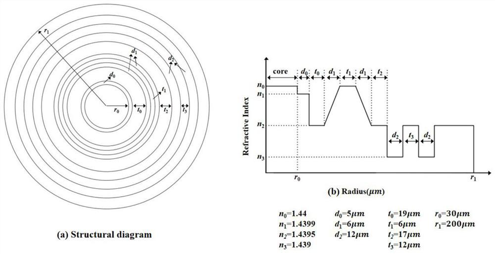
[0040] This embodiment provides a single-mode transmission fiber with trapezoidal refractive index core layer, multiple ravines, large mode field and low bending loss, including two layers of cores with different refractive indices, trapezoidal graded index rings, multiple ravines and cladding; From the inside to the outside, there are fiber core layer, fiber core layer, trapezoidal gradient ring, multiple ravines and cladding.

[0041] Among them: the core layer includes a two-layer core structure, and the refractive index of the outer core is slightly lower than the inner core. Compared with the single-layer core structure, the two-layer core structure can adjust the core and cladding The refractive index difference between them is conducive to the realization of large mode field single-mode transmission.

[0042] The gradient index ring adopts the gradient index ring as the resonant ring, which is resonantly coupled with the mode, which is beneficial to increase the mode fi...

Embodiment 2

[0047]This embodiment is on the basis of embodiment 1:

[0048] In the core layer, the inner core radius r 0 =30μm, the refractive index is 1.44, the thickness d of the outer core ring 0 =5 μm, the refractive index is 1.4399.

[0049] In the trapezoidal refractive index gradient ring, the inner thickness of the trapezoidal refractive index gradient ring d 1 =6μm, the refractive index increase rate is 8.33×10 -5 / μm, distance t between two gradient rings 1 =6μm, refractive index 1.44, outside thickness d 1 =6μm, the refractive index increase rate is -8.33×10 -5 / μm.

[0050] In the multi-gully groove, the thickness d of the first gully 2 =12μm, the refractive index is 1.439, and the distance between two ravines is t 2 =12μm, the refractive index is 1.4395, the thickness d of the second groove 2 =12 μm, the refractive index is 1.439.

[0051] The distance t between the core layer and the trapezoidal refractive index gradient ring 0 =19μm, the interval t between the tr...


PUM

PropertyMeasurementUnit
radiusaaaaaaaaaa
thicknessaaaaaaaaaa
radiusaaaaaaaaaa

Abstract

The invention relates to the technical field of optical fibers, and particularly discloses a large-mode-field single-mode transmission optical fiber which sequentially comprises a fiber core layer, a trapezoidal refractive index gradient ring, a multi-gully groove and a wrapping layer from inside to outside. The fiber core layer comprises two layers of fiber cores, and the refractive index of an outer fiber core is lower than that of an inner fiber core. The refractive index change of the trapezoidal refractive index ring structure is trapezoidal, the refractive index of the inner side is increased from a cladding value to an inner-layer fiber core value, the refractive index value of the middle part is equal to the inner-layer fiber core value, and the refractive index of the outer side is reduced from the inner-layer fiber core value to the cladding value. The multi-gully groove structure comprises two gullies, and the refractive index value of the gullies is lower than the refractive index value of the wrapping layer. The mode field area of the optical fiber can be increased, the bending loss of a fundamental mode can be reduced, the transmission quality of the optical fiber can be improved, and the manufacturability can be improved under the condition of medium-size radius bending.

Description

technical field [0001] The invention relates to the field of optical fiber technology, in particular to a large mode field single-mode transmission optical fiber. Background technique [0002] Optoelectronic interconnection technology is supported by basic technologies such as materials, components, interconnection design and technology. Through optical signal transmission, it connects light sources, interconnection channels, transceivers and other components into one, and it is an efficient way to exchange signals with each other at high speed. Photoelectric hybrid interconnection technology. Its main technologies include design and process of optoelectronic interconnection, design and process technology of optoelectronic printed circuit boards, optoelectronic components and their packaging, etc. [0003] In the actual application process of optoelectronic flexible interconnection substrates, bending is the normal work, and the medium-sized bending radius will cause bendin...

Claims


Application Information

Patent Timeline
Patent Type & Authority Applications(China)
IPC IPC(8): G02B6/02G02B6/028G02B6/036
CPCG02B6/02009G02B6/0285G02B6/03688
Inventor 佘雨来张军华熊显明张文涛杜浩杨松涂闪
Owner GUILIN UNIV OF ELECTRONIC TECH
Why Eureka
Try Eureka