Shadow mask for color CRT

A cathode ray tube and shadow mask technology, applied in the direction of cathode ray tubes/electron beam tubes, discharge tubes, electrical components, etc., can solve the problems of small cross-sectional modulus and relative vibration easily

Inactive Publication Date: 2004-02-25
LG ELECTRONICS INC
View PDF0 Cites 0 Cited by
  • Summary
  • Abstract
  • Description
  • Claims
  • Application Information

AI Technical Summary

Problems solved by technology

[0016] The thickness of most shadow masks 5 is relatively thin, so the value of the section modulus is small, and relative vibration is prone to occur

Method used


Image

  • Shadow mask for color CRT
  • Shadow mask for color CRT
  • Shadow mask for color CRT

Examples


Embodiment Construction

[0035] Preferred embodiments of the present invention will be described below with reference to the accompanying drawings.

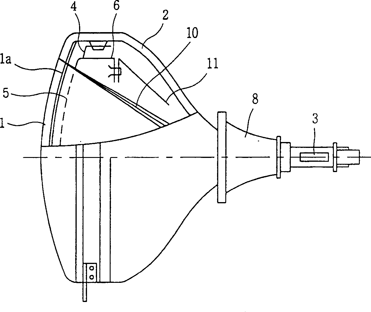
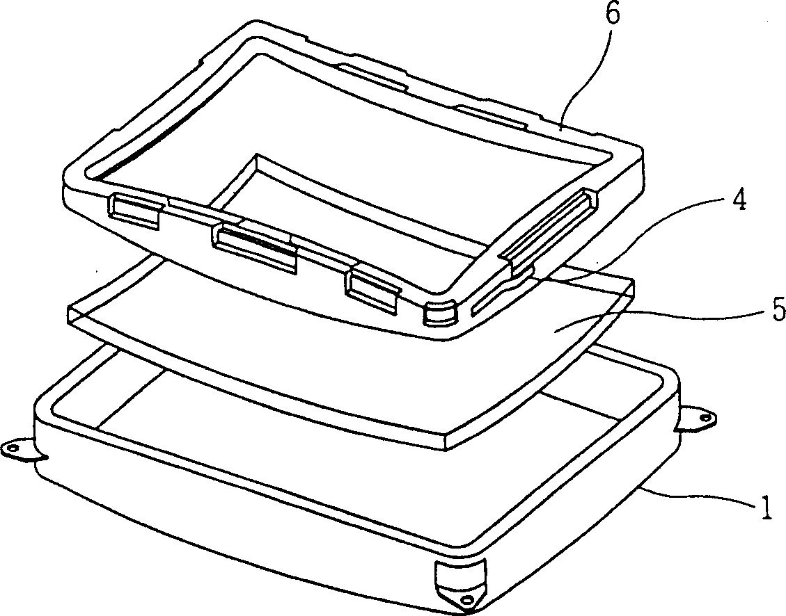
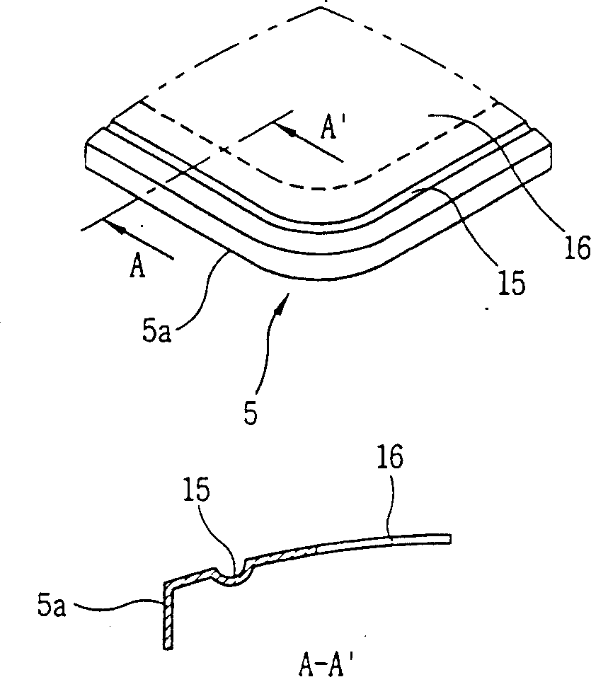
[0036] Such as Figure 6 and Figure 8 As shown, a plurality of debossed ribs 25 according to a preferred embodiment of the present invention are formed on the non-effective surface 25 of the shadow mask 5 along the skirt 5a so as to correspond to each opposite side.

[0037] Wherein, the cross-sectional shape (C-C') of the concave pressure edge protection 25 according to the preferred embodiment of the present invention can be as follows Figure 7 changes shown.

[0038] When forming the concave bezel 25 according to the preferred embodiment of the present invention on the shadow mask 5, in other words, at Figure 8 In the case of Figure 5 The value of the section modulus I against the relative vibration of the effective surface 16 and the skirt 5a of the shadow mask 5 of the present invention can be expressed as [Formula 2] as follows, compared wi...


PUM


Abstract

The present invention relates to a shadow mask comprising an effective surface including electron beam passage holes all over, an ineffective surface having a certain width surrounding the circumference of the effective surface, a skirt portion curved formed on the circumference of the ineffective surface, and concave-compressed beads formed on the ineffective surface along the skirt portion in order to improve the stiffness of the effective surface. The present invention can prevent distortions of a screen by forming the beads on the ineffective surface which is capable of improving stiffness of the shadow mask by increasing a lot value of the section modulus performing a function resisting the relative vibration occurred between the effective surface and skirt portion.

Description

technical field [0001] The present invention relates to a shadow mask for a color CRT (cathode ray tube), in particular to a shadow mask for a color CRT capable of preventing screen deformation (unevenness) due to external vibration and impact by improving the rigidity of the shadow mask. Background technique [0002] In general, the function of the shadow mask installed at the rear end of the glass screen of a color CRT (cathode ray tube) is to make each electron beam radiated from the electron gun accurately strike each color corresponding to the electron beam on the phosphor screen, specifically, It may vibrate due to external vibrations and shocks, and may cause direct damage. Therefore, it is necessary to strengthen the rigidity of the shadow mask in order to obtain high screen definition. [0003] However, unlike other parts, it is impossible to form beads on the effective surface of the shadow mask, and it is possible to form beads on the non-effective surface as the...

Claims


Application Information

Patent Timeline
Patent Type & Authority Patents(China)
IPC IPC(8): H01J29/07
CPCH01J2229/0744H01J29/07
Inventor 金圣大朴相厚
Owner LG ELECTRONICS INC
Why Eureka
Try Eureka