
Automatic rivet mounting method and device

An automatic installation and rivet technology, applied in transportation and packaging, household components, household appliances, etc., can solve the problems of inconsistent depth of multiple rivets, affecting product service life, time-consuming and laborious, and achieving wide applicability and improving installation efficiency. , to ensure the effect of consistency and stability

Pending Publication Date: 2022-02-01
湖南国芯半导体科技有限公司
View PDF0 Cites 0 Cited by
  • Summary
  • Abstract
  • Description
  • Claims
  • Application Information

AI Technical Summary

Problems solved by technology

[0003] In riveting, the rivets realize the connection of parts through their own deformation or interference fit. The current traditional installation method is to manually place the rivets one by one in the predetermined position and then perform pressure riveting. In this process, due to the gap between the substrate and the shell Small size requires high placement accuracy. In order to ensure the pass rate of the product, rivets of appropriate size must be used for riveting. However, due to the small size of the rivets and a large number of rivets mixed in the rivet box, it needs to be manually adjusted to Putting the correct posture into the installation gap or automatically pressing it on an automation device is inefficient; at the same time, since multiple rivets need to be installed on the power semiconductor module, it is not only time-consuming and laborious for workers, but also easy to press during the pressing process. The depth of multiple rivets is not uniform, which affects the service life of the product

Method used


Image

  • Automatic rivet mounting method and device
  • Automatic rivet mounting method and device
  • Automatic rivet mounting method and device

Examples


Embodiment Construction

[0043] The present invention will be further described below in conjunction with accompanying drawing.

[0044] The invention provides an automatic installation method for rivets, comprising:

[0045]S1. Correcting the attitude of the target rivets on the track and not in the pre-installed state to the pre-installed state, and the target rivets are transported to the guide position by the track in the pre-installed state;

[0046] S2. Remove the target rivet located at the guiding position from the track, and move the target rivet to a pre-installed position;

[0047] S3. Using the indenter to press the target rivet at the pre-installation position, so that the target rivet is pressed into the pre-installation position to a predetermined depth.

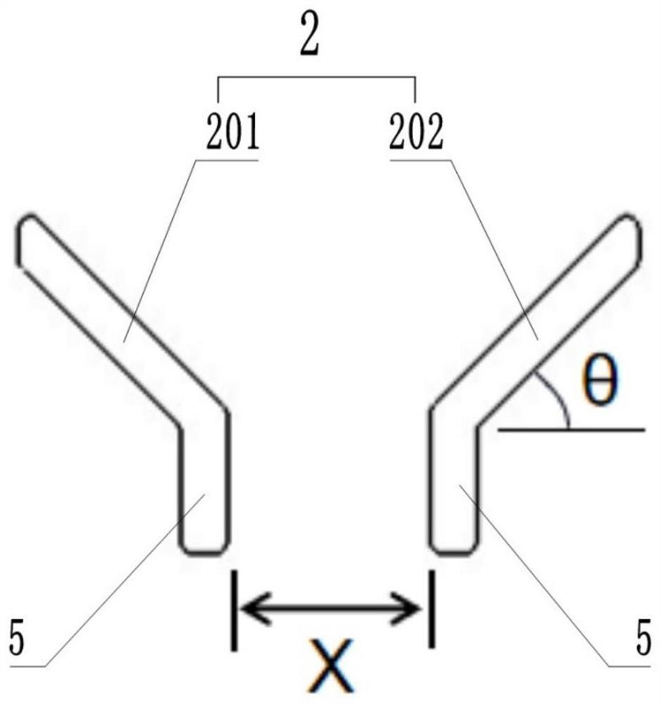
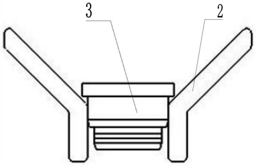
[0048] It should be noted that, if figure 2 As shown, it shows a schematic diagram of the structure of the rivet 3 in a pre-installed state, the central axis of the rivet 3 is kept parallel to the central axis of the track 2 and th...


PUM


Abstract

The invention provides an automatic rivet mounting method and device. The automatic rivet mounting method comprises the steps that S1, the posture of a target rivet which is not in a pre-assembling state on a rail is corrected to be in the pre-assembling state, and the target rivet is conveyed to a guiding position from the rail in the pre-assembling state; S2, the target rivet located at the guiding position is taken down from the track, and the target rivet is moved to a preassembling position; and S3, a pressing head is used for pressing the target rivet located at the pre-assembling position, so that the target rivet is pressed into the pre-assembling position to a preset depth. Based on the technical scheme, the rivet can be quickly, effectively and automatically adjusted to be in a needed form, and subsequent automatic installation is facilitated; efficiency and accuracy are improved, manpower and material resources are saved, and product consistency is guaranteed.

Description

technical field [0001] The invention relates to the technical field of rivet installation, in particular to an automatic installation method and device for rivets. Background technique [0002] At present, most power semiconductor modules use a substrate and a plastic casing as the outermost layer of the module. Since the substrate and the casing are filled with glue, in order to ensure the stability of the connection between the substrate and the casing, the two need to be connected with rivets. [0003] In riveting, the rivets realize the connection of parts through their own deformation or interference fit. The current traditional installation method is to manually place the rivets one by one in the predetermined position and then perform pressure riveting. In this process, due to the gap between the substrate and the shell Small size requires high placement accuracy. In order to ensure the pass rate of the product, rivets of appropriate size must be used for riveting. Ho...

Claims


Application Information

Patent Timeline
IPC IPC(8): B29C65/60B29C65/80B65G47/24B29L31/34
CPCB29C65/601B29C65/80B29C66/84B29C66/929B65G47/24B29C66/9261B29L2031/3481
Inventor 黄蕾戴小平柯攀曾亮刘亮刘洋杜隆纯
Owner 湖南国芯半导体科技有限公司
Learn More