
Tape winding machine and winding method

A winding machine and wrapping technology, applied in the direction of winding strips, transportation and packaging, sending objects, etc., can solve the problems of affecting winding, deformation of high temperature resistant tape, high viscosity of high temperature resistant tape, etc.

Pending Publication Date: 2022-02-01
邓波
View PDF0 Cites 0 Cited by
  • Summary
  • Abstract
  • Description
  • Claims
  • Application Information

AI Technical Summary

Problems solved by technology

However, when the high temperature resistant tape is used for winding, because the high temperature resistant tape is very viscous and easy to deform, after the high temperature resistant tape is clamped by the traditional tape winding machine, it is difficult for the high temperature resistant tape to be removed from the clamping mechanism. Falling off, such as pulling forcibly, may easily cause deformation of the high temperature resistant tape, thus affecting the winding

Method used


Image

  • Tape winding machine and winding method
  • Tape winding machine and winding method
  • Tape winding machine and winding method

Examples


Embodiment 1

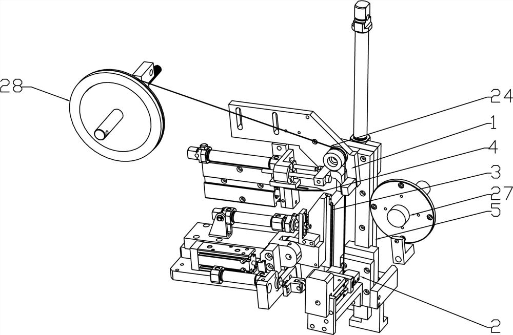
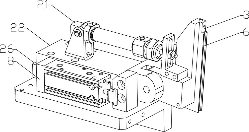
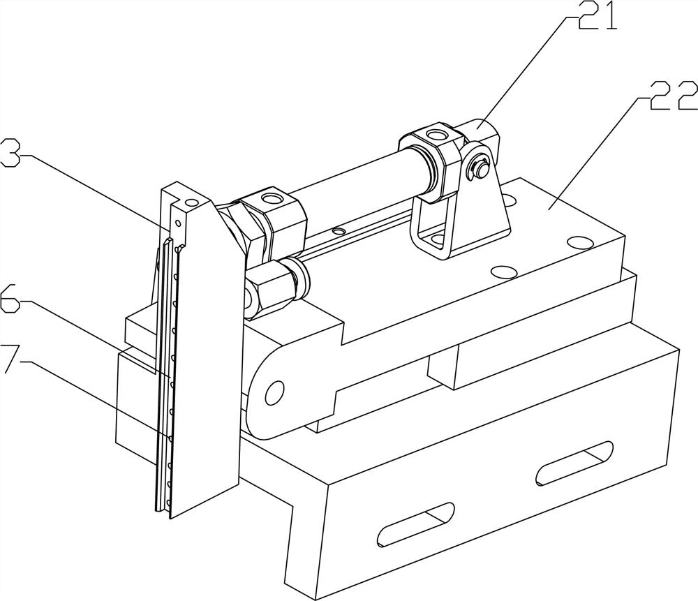
[0033] Such as Figure 1 to Figure 6 As shown, the tape winding machine of the present invention includes an upper clamping mechanism 1 , a lower clamping mechanism 2 , a negative pressure plate 3 and a blade 4 . The upper clamping mechanism 1 is arranged on the upper end of the frame 5 for clamping the adhesive tape 24 . The other end of the adhesive tape 24 is disposed on an adhesive tape reel 28 . The lower clamping mechanism 2 is arranged at the lower end of the frame 5 for clamping the lower end of the adhesive tape 24, and the lower clamping mechanism 2 can move up and down and rotate to one side, and the angle of rotation is ideally 20°- In the range of 60 °, and rotate to the opposite direction of adhesive tape 24 adhesive surface. The negative pressure plate 3 is arranged on one side between the upper clamping mechanism 1 and the lower clamping mechanism 2, and the rear end is connected to a vacuum pump through an air pipe for absorbing the non-stick surface of the ...

Embodiment 2

[0042] A winding method, realized according to the tape winding machine described in embodiment 1, comprises the following steps:

[0043] Step 1: Place the front end of the adhesive tape on the upper clamping mechanism 1 and perform clamping.

[0044] Step 2: The lower clamping mechanism 2 uses the fourth cylinder 15 to slide up first to clamp the lower end of the tape, and then slide down to pull out the tape. During the process of pulling the tape, the upper clamping mechanism 1 releases the tape.

[0045] Step 3: After the lower clamping mechanism 2 has finished pulling the tape, use the first cylinder 8 to push the negative pressure plate 3 to the vicinity of the tape or stick it to the tape, and the vacuum pump is turned on, and the negative pressure plate 3 Negative pressure is generated to attract the non-stick side of the tape.

[0046] Step 4: The claws of the lower clamping mechanism 2 are opened, the tape is released, and then rotated at a certain angle (20°-60°) ...


PUM


Abstract

The invention discloses a tape winding machine suitable for a high-viscosity adhesive tape and a winding method. According to the technical scheme, the tape winding machine comprises an upper clamping mechanism arranged at the upper end of a rack and used for clamping an adhesive tape; a lower clamping mechanism which is arranged at the lower end of the rack, is used for clamping the lower end of the adhesive tape, and can move up and down and rotate towards one side; a negative pressure plate which is arranged on one side between the upper clamping mechanism and the lower clamping mechanism, is used for adsorbing the non-sticky surface of the adhesive tape, and can move back and forth and rotate towards one side; a blade which is arranged on one side of the negative pressure plate and is used for cutting off the adhesive tape. The tape winding device has the advantages that after the high-temperature-resistant adhesive tape with the appropriate length is pulled out through the lower clamping mechanism, the high-temperature-resistant adhesive tape can fall off from the lower clamping mechanism very easily, deformation of the adhesive tape cannot be caused, then the winding quality and efficiency can be improved, and faults of a machine can be reduced.

Description

technical field [0001] The invention relates to a tape winding machine. Background technique [0002] The tape winding machine is an automatic equipment that winds the tape onto the circumferential surface of the wound workpiece (such as an amorphous alloy strip roll). The traditional tape winding machine usually winds the tape onto the workpiece to be wound, and then cuts the tape with a blade. However, when the high temperature resistant tape is used for winding, because the high temperature resistant tape is very viscous and easy to deform, after the high temperature resistant tape is clamped by the traditional tape winding machine, it is difficult for the high temperature resistant tape to be removed from the clamping mechanism. Falling off, such as pulling forcibly, will easily cause deformation of the high temperature resistant tape, thus affecting the winding. Contents of the invention [0003] The technical problem to be solved by the present invention is to prov...

Claims


Application Information

Patent Timeline
Patent Type & Authority Applications(China)
IPC IPC(8): B65H20/16B65H35/07
CPCB65H20/16B65H35/0033B65H2701/377
Inventor 邓波
Owner 邓波
Learn More