
Oil duct structure of VVT (variable valve timing) system

An oil channel and pressure cavity technology, applied in the field of oil channel structure, can solve the problems of failure of oil channel switching mechanism, complicated operation of OCV valve, general circulation effect, etc., to achieve the effects of simple assembly, improved service life, and avoidance of direct impact.

Inactive Publication Date: 2015-06-10
TAIZHOU DEERFU AUTOMOBILE PARTS
View PDF7 Cites 1 Cited by
  • Summary
  • Abstract
  • Description
  • Claims
  • Application Information

AI Technical Summary

Problems solved by technology

[0005] In the prior art, the valve body of the OCV valve is usually provided with a three-way annular groove, and a radial through hole communicating with the inner cavity of the valve body is arranged in the groove, and a filter screen is covered in the groove, and the filter screen is usually made of a metal strip. They are connected end to end and welded into a complete annular filter screen. Therefore, when the OCV valve needs to be cleaned, it can only destroy the filter screen to make the radial through holes in the groove unobstructed, and then clean it; the existing defects are: 1 1. The filter screen is a consumable accessory; 2. The operation of cleaning the OCV valve is cumbersome
[0008] Among them, when the spool moves in the coil, the chambers on the upper and lower sides of the spool circulate air through the gap between the spool and the coil. The circulation effect is general and there is a certain resistance to the movement of the spool.
Moreover, the ejector rod is fixed in the through hole in the middle of the valve core. After a period of use, the ejector rod has a potential safety hazard of loosening (that is, the ejector rod is embedded deeper in the valve core), resulting in failure of the oil circuit switching mechanism.

Method used


Image

  • Oil duct structure of VVT (variable valve timing) system
  • Oil duct structure of VVT (variable valve timing) system
  • Oil duct structure of VVT (variable valve timing) system

Examples


Embodiment 1

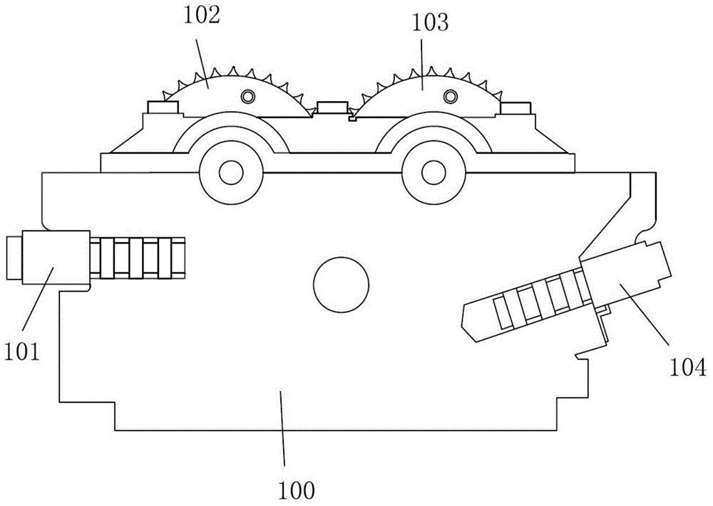
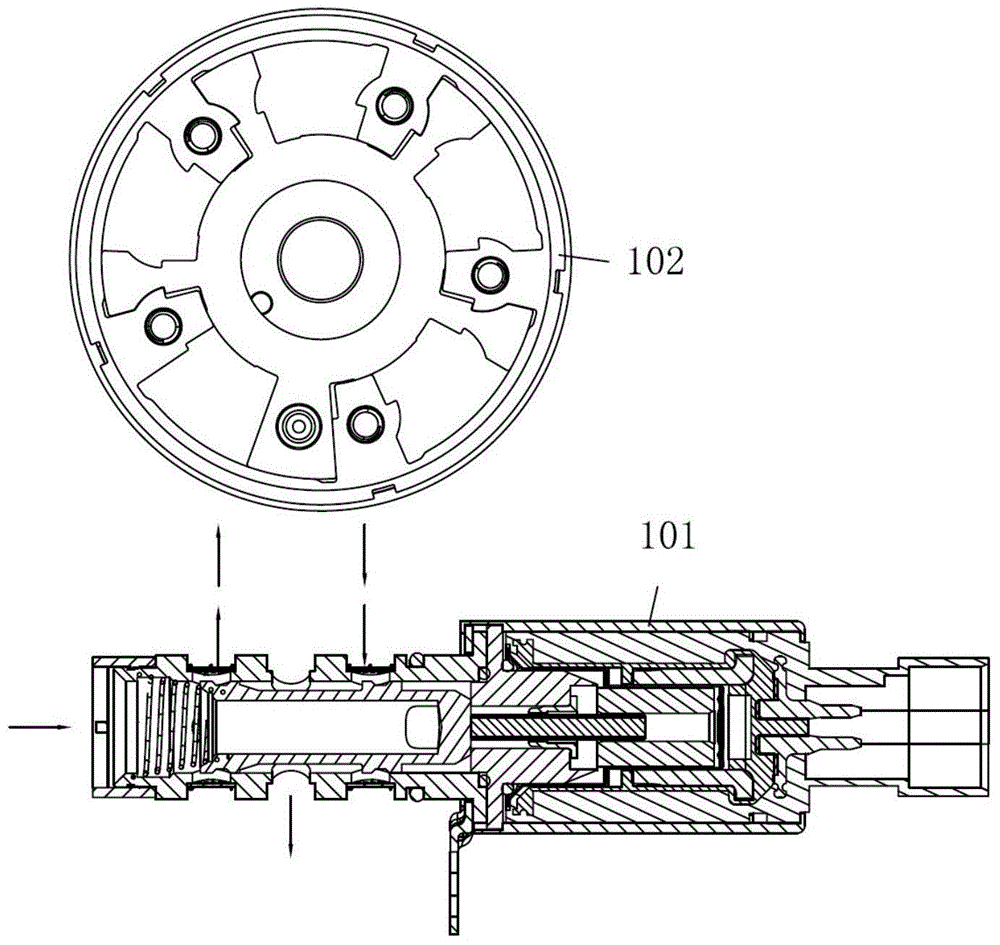
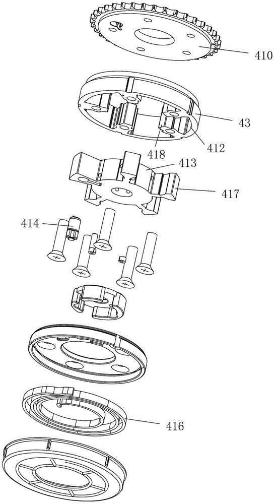
[0051] Embodiment 1: An oil passage structure of a VVT system, including a camshaft phaser and an OCV valve. The camshaft phaser includes a rotor 44 and a stator 43. The stator 43 is provided with several pressure-holding chambers, and the base of the rotor 44 The outer side is provided with evenly distributed blades 42, the blades 42 extend into the pressure holding chamber and divide the pressure holding chamber into an advanced angle pressure holding chamber and a late angle pressure holding chamber 41, the rotor base and the blades are integrated structure, the rotor The outer peripheral surface 413 of the base and the inner peripheral surface 418 of the stator are bonded without damping and are fluid-tight, and the outer peripheral surface 417 of the blade is bonded to the inner peripheral surface 412 of the pressure-holding chamber without damping and are fluid-tight. The integral structure of the rotor base and the blades of the present invention can effectively improve ...

Embodiment 2

[0065] Embodiment 2: This embodiment is basically the same as Embodiment 1, the difference is that the ejector rod 33 and the reversing rod 34 of the OCV valve are of an integrated structure, and the front end of the ejector rod 33 is against the valve core 31 Central; the lower end of the skeleton is connected with a base, and the side of the base facing the valve core is provided with a magnetic isolation sheet 32; The through hole and the magnetic isolation sheet 32. The design of the magnetic isolation sheet 32 ​​makes the solenoid valve assembly more efficient and more practical. This embodiment not only solves the matching problem caused by looseness between the ejector rod and the valve core, but also saves assembly steps and reduces costs. In addition, in this embodiment, exhaust grooves can be provided on the peripheral side of the valve core as required to ensure smooth flow of air between the chambers on the upper and lower sides of the valve core. In this embodim...


PUM


Abstract

The invention relates to the technical field of automotive VVT (variable valve timing) systems, in particular to an oil duct structure of a VVT system. The oil duct structure comprises a cam shaft phaser and an OCT (oil control valve), wherein the cam shaft phaser comprises a rotor and a stator, a plurality of pressure maintaining cavities are formed in the stator, uniformly distributed blades are arranged on the outer side of a base of the rotor and extend into the pressure maintaining cavities to divide the pressure maintaining cavities into feed angle pressure maintaining cavities and lag angle pressure maintaining cavities, the base of the rotor and the blades adopt an integrated structure, an outer circumferential surface of the base of the rotor and an inner circumferential surface of the stator are in non-damping attachment and in liquid sealing, and an outer circumferential surface of each blade and an inner circumferential surface of each pressure maintaining cavity are in non-damping attachment and in liquid sealing. The processing accuracy can be effectively improved by means of an integrated structure, meanwhile, assembling errors can be avoided, matched friction force between the rotor and the stator is reduced to the minimum, an additional sealing system is not required, and the service life is prolonged; hydraulic sealing overflowing is performed by the stator and the rotor through buffer matching of a buffer groove and a bulge, direct collision of the stator and the rotor is avoided, and mute operation is completely realized.

Description

technical field [0001] The invention belongs to the technical field of automobile VVT ​​systems, in particular to an oil passage structure of the VVT ​​system. Background technique [0002] When the engine is under different working conditions, the ECU of the car will control the action of the OCV valve, and the reversing rod inside the OCV valve will move forward and backward to change the oil passage. If the oil passage is different, a certain amount of oil will be introduced into the cam phase adjuster. There are blades between the rotor and the stator of the phase adjuster, which divides a chamber into two spaces. When the oil enters from one side, the timing will be advanced, and when the oil enters from the other side, the timing will be delayed. At the same time, the amount of engine oil entering the cam phase adjuster determines the variation of the valve timing. The engine system controls the change of the oil passage of the OCV valve to realize the advance or lag o...

Claims


Application Information

Patent Timeline
Patent Type & Authority Applications(China)
IPC IPC(8): F01L1/344
CPCF01L1/3442F01L2001/34423F01L2001/3443F01L2001/3444F01L2001/34483
Inventor 王俊杰王锦富林钰李建全柯孔辉袁文东应君敏唐佳陆城波苏珏
Owner TAIZHOU DEERFU AUTOMOBILE PARTS
Learn More