
Top plate U rib connecting structure and construction method thereof

A technology for connecting structures and construction methods, applied to bridge parts, erecting/assembling bridges, bridge materials, etc., can solve problems such as fatigue damage at the joint of U-ribs, weakening of U-rib stiffness, etc. Effect of reducing stiffness and avoiding fatigue problems

Pending Publication Date: 2022-02-01
TONGJI UNIV ARCHITECTURAL DESIGN INST GRP CO LTD
View PDF0 Cites 0 Cited by
  • Summary
  • Abstract
  • Description
  • Claims
  • Application Information

AI Technical Summary

Problems solved by technology

There are two main types of roof U-rib connection structures currently used: one is to use the U-rib embedding section and the lining plate to connect the U-rib sections of the two sections through welding; the advantage of this connection structure is that it is simple in structure, The rigidity is not weakened, but the disadvantage is that the U-rib joint is prone to fatigue damage
The second is to use U-rib webs to add splicing plates, and use high-strength bolts to connect instead of welded joints. However, in order to solve the operation of high-strength bolts, it is necessary to open hand holes in the bottom plate at the U-rib connection; the advantages of this connection structure are: The U-rib is connected by high-strength bolts to avoid fatigue damage. The disadvantage is that the U-rib bottom plate has a hand hole, which greatly weakens the rigidity of the U-rib.

Method used


Image

  • Top plate U rib connecting structure and construction method thereof
  • Top plate U rib connecting structure and construction method thereof
  • Top plate U rib connecting structure and construction method thereof

Examples


Embodiment 1

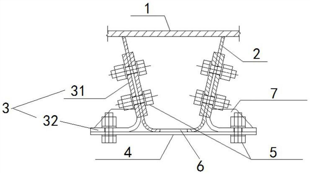
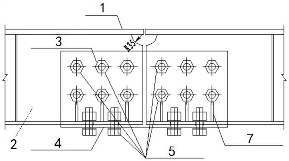
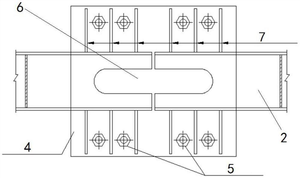
[0037] A roof U-rib connection structure, such as Figure 1~3 As shown, it includes top plate 1, U rib 2, web connecting plate 3, bottom plate connecting plate 4, high-strength bolts 5 and hand holes 6. The U rib 2 is welded on the lower surface of the top plate 1, and the web connecting plate 3 and the bottom plate connecting plate 4 are detachably arranged at the joint of the U rib 2 through high-strength bolts 5 . Wherein, the web connecting plate 3 is arranged on the outer side of the U rib 2, and the structure is as follows Figure 4 As shown, it includes a U rib connecting portion 31 and a bottom plate connecting portion 32 arranged at an angle. Bolt holes 33 are provided, and the bottom surface of U rib 2 is provided with hand holes 6, such as figure 1 As shown, the U-rib connecting portion 31 is fixed on the side wall of the U-rib 2 by high-strength bolts 5, and the bottom-plate connecting portion 32 is fixed on the bottom-plate connecting plate 4 by high-strength bo...

Embodiment 2

[0039] A U-rib connection structure of the top plate, stiffening ribs 7 are arranged on the bottom plate connection part 32 to strengthen the structural strength, and the rest of the structure is the same as that of Embodiment 1.

[0040] The preparation and construction methods of the roof U-rib connection structure of this embodiment are as follows:

[0041] The first step: cutting and processing the web connecting plate 3 in the factory, transforming the original rectangular connecting plate into an L-shaped connecting plate, and setting stiffeners 7 to weld it for reinforcement;

[0042] Step 2: Pre-assemble the sections in the factory, locate the high-strength bolt holes on the U rib 2, the web connecting plate 3, and the bottom plate connecting plate 4, and precisely make the holes at the bottom of the U rib 2 at the end of the segment on both sides A hand hole 6 is provided to facilitate the tightening of high-strength bolts 5;

[0043] Step 3: At the splicing site, us...


PUM


Abstract

The invention relates to a top plate U rib connecting structure and a construction method thereof. The top plate U rib connecting structure comprises a top plate (1) and a U rib (2) welded on the top plate (1), and is characterized in that the U rib (2) is provided with a web connecting plate (3) and a bottom plate connecting plate (4) at the section splicing position, the web connecting plate (3) comprises a U rib connecting part (31) and a bottom plate connecting part (32), the U rib connecting part (31) is connected with the U rib (2), and the bottom plate connecting part (32) is connected with the bottom plate connecting plate (4). Compared with the prior art, the U-rib splicing plate is improved, and the bottom plate connecting plate and the bolts are additionally arranged, so that the problems of fatigue at the seam of the U ribs of the existing top plate and weakening of the rigidity of the U ribs are solved.

Description

technical field [0001] The invention relates to the technical field of bridge engineering, in particular to a roof U-rib connection structure and a construction method thereof. Background technique [0002] The orthotropic steel bridge deck is a structural form composed of mutually perpendicular roofs, longitudinal ribs and diaphragms connected by welds and working together. It has light weight, large bearing capacity, wide application range, fast construction speed and beautiful appearance. Features. The longitudinal ribs of orthotropic steel decks usually adopt U-shaped stiffener structure. [0003] With the large-scale application of steel bridges, more and more attention has been paid to the fatigue cracking of orthotropic steel bridge decks, especially the construction site connection structure of U-rib roof at segmental splices, which is often the focus of fatigue problems. There are two main types of roof U-rib connection structures currently used: one is to use the...

Claims


Application Information

Patent Timeline
Patent Type & Authority Applications(China)
IPC IPC(8): E01D21/00E01D19/12E01D101/30
CPCE01D21/00E01D19/125E01D2101/30
Inventor 孙旭霞邓青儿励晓峰郑本辉吴用贤孙丽明闫文华陈轶迪杨志白志娟
Owner TONGJI UNIV ARCHITECTURAL DESIGN INST GRP CO LTD
Learn More