Cable tunnel cable heating monitoring and fire suppression system

A cable tunnel and fire technology, applied in the field of electric power, can solve problems such as increased leakage current, difficult to find and deal with, insulation aging, etc., and achieve the effect of preventing the deterioration of the fire

Pending Publication Date: 2022-02-01
国网甘肃省电力公司酒泉供电公司
View PDF0 Cites 0 Cited by
  • Summary
  • Abstract
  • Description
  • Claims
  • Application Information

AI Technical Summary

Problems solved by technology

[0002] As the power transmission part in the power grid, the reliability of the cable is one of the keys to ensure the stable operation of the entire power grid. The cable includes overhead cables and underground cables. The underground cables are laid in the cable tunnel. Since the cable tunnel is in a relatively closed state, Therefore, its maintenance and inspection are very difficult, especially when the cable joint is heated and a fire hazard occurs in the cable tunnel, it is difficult to find and deal with it in time.
[0003] All kinds of faults at the cable joints are not a sudden process, but because the temperature at the joints continues to rise, the insulation gradually ages, the leakage current gradually increases, and breakdown occurs after reaching a certain level. Therefore, how to accurately monitor is one of the difficult problems. On the other hand, when the cable joint heats up and causes a fire hazard, how to deal with it in time to prevent the accident from further expanding is another difficult problem.

Method used


Image

  • Cable tunnel cable heating monitoring and fire suppression system
  • Cable tunnel cable heating monitoring and fire suppression system
  • Cable tunnel cable heating monitoring and fire suppression system

Examples


Embodiment Construction

[0028] Below in conjunction with accompanying drawing, the present invention is described in further detail:

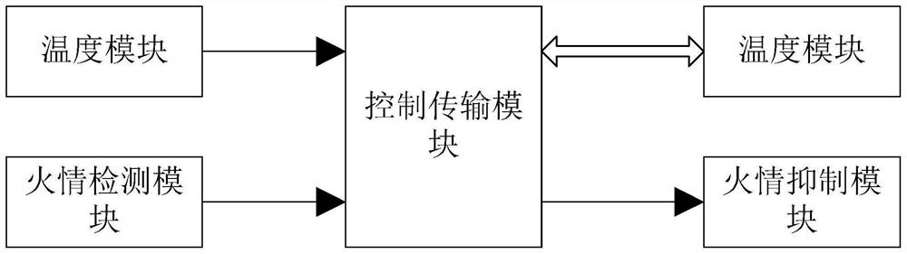
[0029] A cable tunnel cable heating monitoring and fire suppression system provided by the present invention includes a temperature detection module, a fire detection module, a control transmission module and a fire suppression module;

[0030] The temperature module is arranged at the cable joint, and is used to detect the temperature signal at the cable joint and transmit it to the control transmission module;

[0031] The fire detection module is used to detect fire parameters in the cable tunnel and transmit them to the suppression transmission module;

[0032] The suppression transmission module is used to receive the parameter information output by the temperature module and the fire detection module, and judge whether a fire occurs, upload the parameter information to the monitoring center and output a trigger control signal to the fire suppression module when ...


PUM


Abstract

The invention provides a cable tunnel cable heating monitoring and fire suppression system. The system comprises: a temperature module which is disposed at a cable joint, and is used for detecting a temperature signal at the cable joint, and transmitting the temperature signal to a control transmission module; a fire behavior detection module used for detecting fire behavior parameters in the cable tunnel and transmitting the fire behavior parameters to a suppression transmission module; the suppression transmission module which is used for receiving the parameter information output by the temperature module and the fire behavior detection module, judging whether a fire behavior occurs or not, uploading the parameter information to a monitoring center and outputting a trigger control signal to a fire behavior suppression module when the fire behavior occurs; and the fire behavior suppression module which receives the trigger control signal output by the suppression transmission module and executes a fire behavior suppression action. By adopting the cable tunnel cable heating monitoring and fire suppression system, the temperature of the cable joint in the cable tunnel can be monitored in real time, cable joint overheating fault warning can be carried out in time, fire in the tunnel can be accurately monitored, early warning and processing can be carried out in time, and continuous, stable and reliable operation of the cable can be fully guaranteed.

Description

technical field [0001] The invention relates to the field of electric power, in particular to a cable tunnel cable heating monitoring and fire suppression system. Background technique [0002] As the power transmission part in the power grid, the reliability of the cable is one of the keys to ensure the stable operation of the entire power grid. The cable includes overhead cables and underground cables. The underground cables are laid in the cable tunnel. Since the cable tunnel is in a relatively closed state, Therefore, its maintenance and inspection are very difficult, especially when the cable joint heats up and a fire hazard occurs in the cable tunnel, it is difficult to find and deal with it in time. [0003] All kinds of faults at the cable joints are not a sudden process, but because the temperature at the joints continues to rise, the insulation gradually ages, the leakage current gradually increases, and breakdown occurs after reaching a certain level. Therefore, h...

Claims


Application Information

Patent Timeline
IPC IPC(8): G01D21/02G01K1/02G01K1/024G05B19/042G08C17/02A62C37/38A62C3/16
CPCG01D21/02G01K1/02G01K1/024G05B19/0428A62C3/16A62C37/38G08C17/02
Inventor 闫先国沈永斌石磊赵年年魁五军林莉李锦涛金鑫付燕焦多峤吴向向杨丹琪刘文强
Owner 国网甘肃省电力公司酒泉供电公司
Why Eureka
Try Eureka