
Safety protection system for lithium battery test chamber

A safety protection and test box technology, applied in fire rescue and other directions, can solve the problems of delayed fire extinguishing, harmful gas leakage, no on-site monitoring and remote monitoring functions, etc., to prevent fire deterioration and achieve the effect of high degree of automation

Inactive Publication Date: 2018-10-26
SHANGHAI INST OF TECH
View PDF4 Cites 10 Cited by
  • Summary
  • Abstract
  • Description
  • Claims
  • Application Information

AI Technical Summary

Problems solved by technology

[0005] 1) The fire monitoring function is also relatively simple. A single detection signal is often used to judge the fire and put out the fire. For example, the fixed temperature detection temperature threshold will trigger the controller to alarm, which is prone to missed alarms and other situations.
[0006] 2) Without on-site monitoring and remote monitoring functions, it is impossible to monitor the fire situation in real time and discover potential hidden dangers, which delays the best time to put out the fire
[0007] 3) Usually there is no automatic fire extinguishing function, and the operator needs to observe the detection process of the lithium battery through the observation window of the test box. If an abnormal state is found, it is necessary to manually cut off the power supply and stop the relevant test work; if a fire occurs, the test box must also be opened Use a hand-held fire extinguishing device to extinguish the fire, which may easily cause harmful gas leakage and battery explosion, threatening the personal safety of the operator and causing property loss of the company

Method used


Image

  • Safety protection system for lithium battery test chamber
  • Safety protection system for lithium battery test chamber
  • Safety protection system for lithium battery test chamber

Examples


Embodiment Construction

[0056] The present invention will be described in detail below in conjunction with specific embodiments. The following examples will help those skilled in the art to further understand the present invention, but do not limit the present invention in any form. It should be noted that those skilled in the art can make several changes and improvements without departing from the concept of the present invention. These all belong to the protection scope of the present invention.

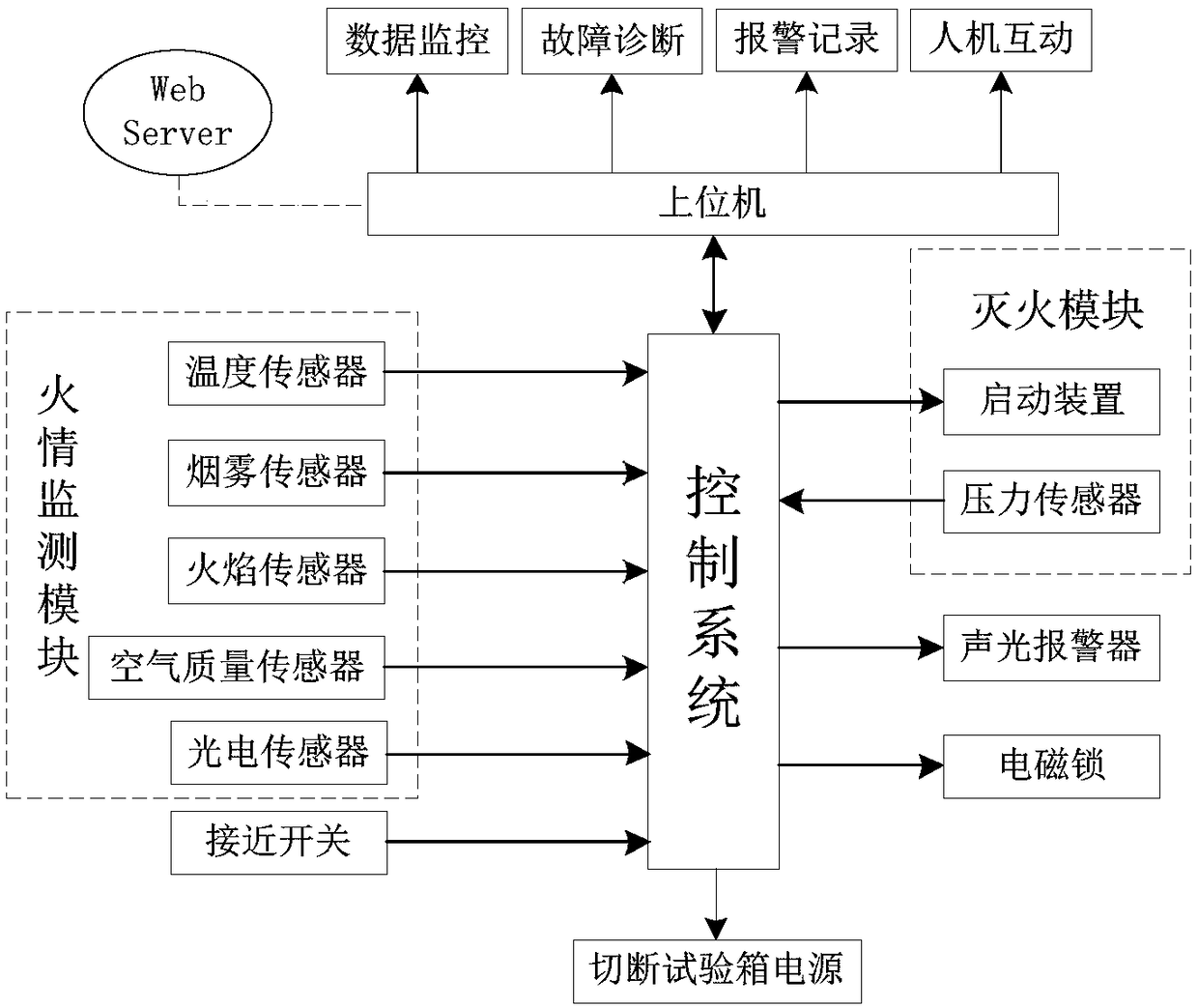
[0057] figure 1 The schematic diagram of the principle of the safety protection system of the lithium battery test box provided by the present invention, as figure 1 As shown, the system may include: a fire monitoring module, a fire extinguishing module, a control system, and a host computer; the fire monitoring module, the fire extinguishing module, and the host computer are respectively connected to the control system by communication; wherein:

[0058]The fire monitoring module is used to collect th...


PUM


Abstract

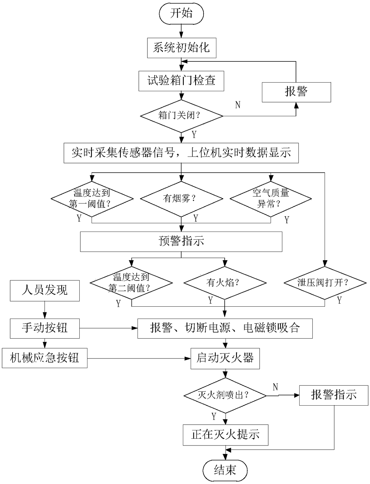
The invention provides a safety protection system for a lithium battery test chamber. The safety protection system comprises a fire monitoring module, a fire extinguishment module, a control system and an upper computer. The fire monitoring module is used for acquiring monitoring data of the lithium battery test chamber and transmitting the monitoring data to the control system. The control systemis used for transmitting the monitoring data to the upper computer and generating a start signal for controlling the fire extinguishment module to carry out the fire extinguishment task when the monitoring data are abnormal. The fire extinguishment module is used for carrying out the fire extinguishment task according to the start signal. The upper computer is used for receiving and displaying the monitoring data transmitted by the control system and providing a user interaction interface so that the control system can carry out corresponding operation according to a control signal input by auser. By means of the safety protection system, the monitoring data inside the lithium battery test chamber can be judged intelligently; the early warning effect is achieved; when fire breaks out, the fire extinguishment module can be started automatically for controlling the fire; the whole process is high in automation degree; and the fire can be effectively prevented from getting worse.

Description

technical field [0001] The invention relates to the technical field of lithium battery safety, in particular to a safety protection system for a lithium battery test box. Background technique [0002] In recent years, the government has vigorously promoted new energy application technologies, and a large number of power lithium battery projects have been applied. However, the power lithium battery industry lacks unified norms and standards, resulting in uneven management levels of production enterprises in the entire industry, and great hidden dangers in product quality. . Fires and even explosions caused by lithium-ion batteries occur frequently, and the safety of lithium-ion batteries has aroused great concern from the society. [0003] Lithium battery test is an important link in the field of lithium battery production and inspection. It is necessary to conduct various limit performance tests on lithium batteries, including overcharge and overdischarge, high temperature ...

Claims


Application Information

Patent Timeline
Patent Type & Authority Applications(China)
IPC IPC(8): A62C3/16A62C37/40A62C37/50
CPCA62C3/16A62C37/40A62C37/50
Inventor 尚慧琳杨文祥王天宇徐进吴俊军毕延良路琛蔡欣淼
Owner SHANGHAI INST OF TECH
Learn More