Solid waste thermal cracking incinerator

A solid waste, thermal cracking technology, applied in incinerators, combustion methods, combustion types, etc., can solve the problems of complex domestic waste materials, difficult to achieve ash and slag thermal reduction rate, flue gas emissions, and high moisture content. Eliminate the cost of centralized processing and transfer, ensure continuous, stable and reliable operation, and ensure the effect of efficient and clean disposal

Pending Publication Date: 2022-04-12
山东百川同创能源有限公司
View PDF0 Cites 0 Cited by
  • Summary
  • Abstract
  • Description
  • Claims
  • Application Information

AI Technical Summary

Problems solved by technology

For hilly mountainous areas or county-level urban areas where domestic waste generation is small, the investment and operation costs of large and medium-sized centralized incineration power generation projects are relatively high, and waste raw materials are not convenient for long-distance transportation, and the heat produced is inconvenient for local recycling, so it is not suitable for Household waste is incinerated separately for power generation. At present, the thermal cracking process is mainly used for reduction disposal
[0004] However, under the background of no large-scale promotion of classified collection and disposal of domestic waste or poor classification, the composition of domestic waste materials is complicated, the moisture content is high, and there is generally no independent sorting or drying process before pyrolysis
The existing small and medium-sized distributed domestic waste thermal cracking systems mostly adopt the fixed-bed simmering process. Due to the uneven characteristics of the waste raw materials and the defects of the furnace body structure, it is easy to cause problems such as burn-through and partial burning, flameout, and smoke leakage. As a result, continuous and stable operation is not possible, the amount of waste disposal is limited, the tar and dioxin-like harmful substances in the flue gas are not completely decomposed, and additional fuel needs to be supplemented. It is difficult to meet the technical specifications for domestic waste incineration treatment

Method used


Image

  • Solid waste thermal cracking incinerator
  • Solid waste thermal cracking incinerator
  • Solid waste thermal cracking incinerator

Examples


Embodiment Construction

[0025] It should be noted that the following detailed description is exemplary and intended to provide further explanation of the present invention. Unless defined otherwise, all technical and scientific terms used herein have the same meaning as commonly understood by one of ordinary skill in the art to which this invention belongs.

[0026] It should be noted that the terminology used here is only for describing specific implementations, and is not intended to limit the exemplary implementations according to the present application. As used herein, unless the context clearly dictates otherwise, the singular is intended to include the plural, and it should also be understood that when the terms "comprising" and / or "comprising" are used in this specification, they mean There are features, steps, operations, means, components and / or combinations thereof.

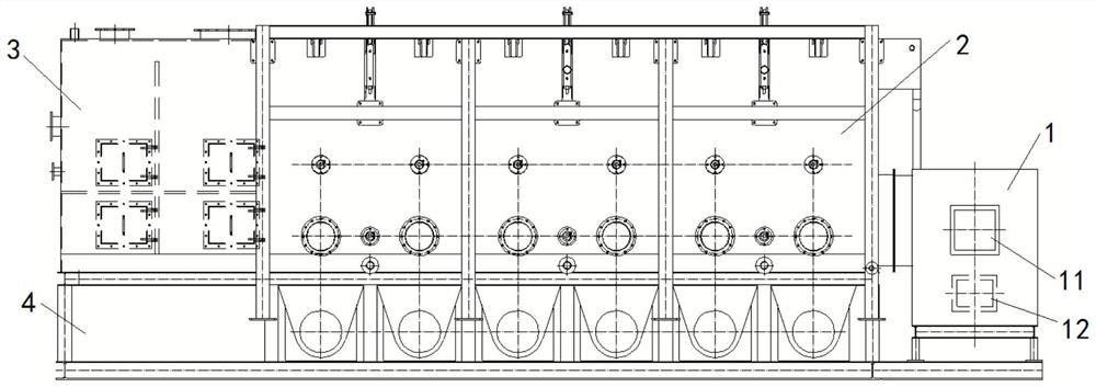
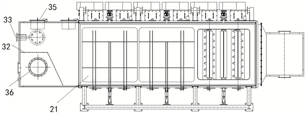
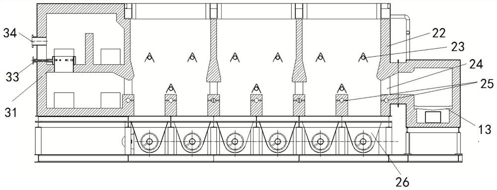
[0027] like image 3 and Figure 5 As shown, a thermal cracking incinerator for solid waste includes a thermal cracking ...


PUM


Abstract

The invention belongs to the technical field of solid waste treatment, and relates to a solid waste thermal cracking incinerator which comprises a thermal cracking chamber and a disturbance device in the thermal cracking chamber. The disturbance device comprises a rotating pipe and a V-shaped guide plate, the inner side walls of two side plates of the V-shaped guide plate are externally tangent to the outer wall of the rotating pipe, and the two ends of the disturbance device are connected with the side walls of the thermal cracking chamber respectively; the driving device is connected with the two ends of the rotating pipe, so that the rotating pipe of the disturbance device rotates and stops within the range of 360 degrees relative to the side wall of the thermal cracking chamber. The problems of burning through, burning deviation, flameout and the like in the solid material burning process are solved, and the whole system can operate continuously and stably.

Description

technical field [0001] The invention belongs to the technical field of solid waste treatment, and in particular relates to a thermal cracking incinerator for solid waste. Background technique [0002] The information disclosed in this background section is only intended to increase the understanding of the general background of the present invention, and is not necessarily taken as an acknowledgment or any form of suggestion that the information constitutes the prior art already known to those skilled in the art. [0003] At present, large and medium-sized centralized direct combustion incineration power generation and small and medium-sized distributed thermal cracking incineration are the main ways to reduce the amount of solid waste that can be combusted, such as domestic waste, and some other fields that require thermal cracking and incineration. . For hilly mountainous areas or county-level urban areas where domestic waste generation is small, the investment and operat...

Claims


Application Information

Patent Timeline
Patent Type & Authority Applications(China)
IPC IPC(8): F23G5/027F23G5/04F23G5/14F23G5/44F23L9/00
Inventor 董磊沙响玲徐鹏举于杰季哲常加富
Owner 山东百川同创能源有限公司
Why Eureka
Try Eureka