Toner bin connecting structure of split type toner cartridge

A connection structure and separate technology, which is applied in the direction of electric recording process applying charge pattern, equipment of electric recording process applying charge pattern, electric recording technique, etc. problems, to change the complex installation steps, reduce toner leakage, easy maintenance and cleaning

Pending Publication Date: 2022-02-01
珠海天安华泰科技有限公司
View PDF0 Cites 0 Cited by
  • Summary
  • Abstract
  • Description
  • Claims
  • Application Information

AI Technical Summary

Problems solved by technology

[0003] Most of the existing toner cartridges are integral, and with the change of use needs, there are more and more split toner cartridges, but whether it is an integral toner cartridge or a split toner cartridge, most of the powder bins are fixed, only when adding powder, The toner cartridge needs to be disassembled as a whole
Taking split toner cartridges as an example, some toner cartridges need to separate the waste toner bin from the toner bin, and then remove the magnetic roller installed in the toner bin to add toner. The overall toner addition process is very cumbersome.
In addition, an agitator is generally installed inside the powder bin of the split type toner cartridge to increase the uniformity of powder output. However, during the installation process of the traditional toner cartridge, due to poor sealing, it will cause powder leakage. At the same time, the structure of the toner cartridge is complicated and the assembly is troublesome.

Method used


Image

  • Toner bin connecting structure of split type toner cartridge
  • Toner bin connecting structure of split type toner cartridge
  • Toner bin connecting structure of split type toner cartridge

Examples


Embodiment Construction

[0031] The following will clearly and completely describe the technical solutions in the embodiments of the present invention with reference to the accompanying drawings in the embodiments of the present invention. Obviously, the described embodiments are only some, not all, embodiments of the present invention. Based on the embodiments of the present invention, all other embodiments obtained by persons of ordinary skill in the art without making creative efforts belong to the protection scope of the present invention.

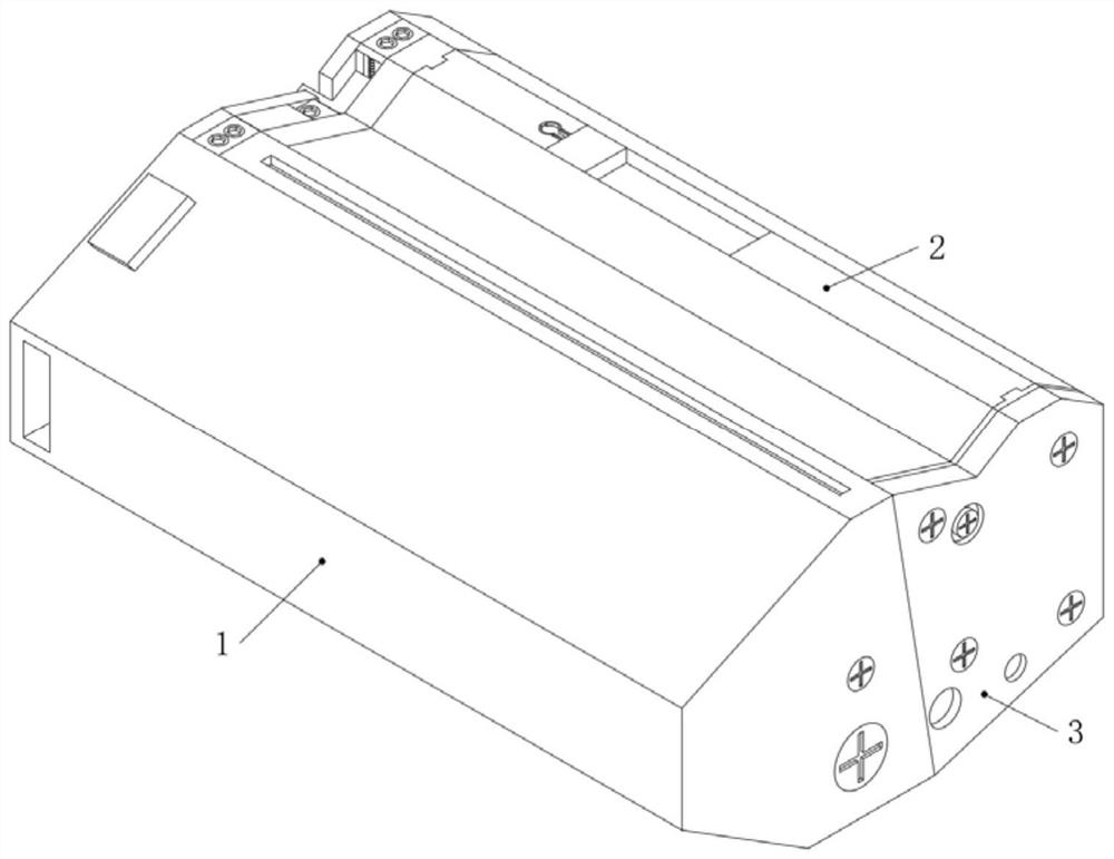
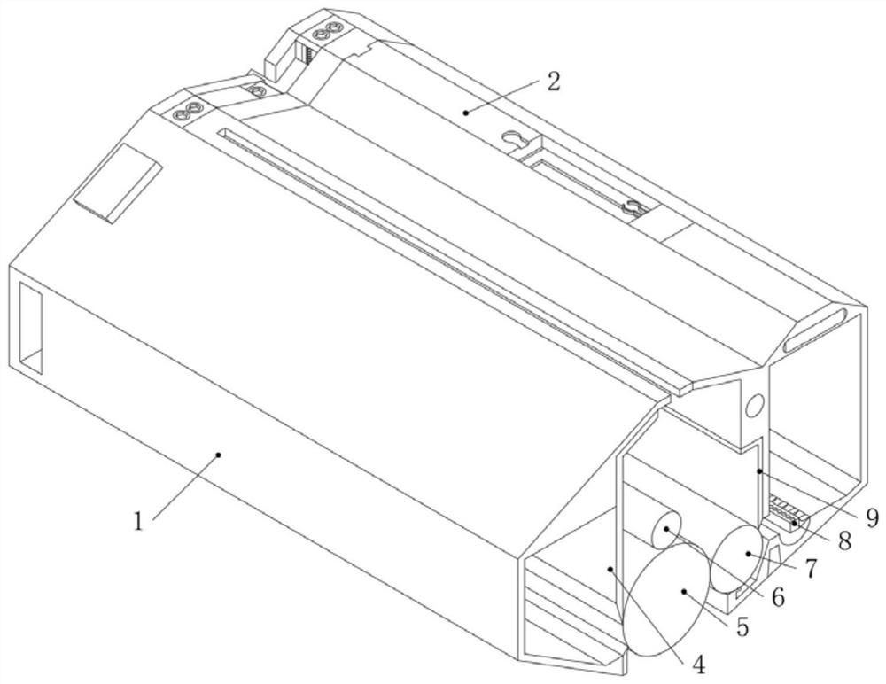
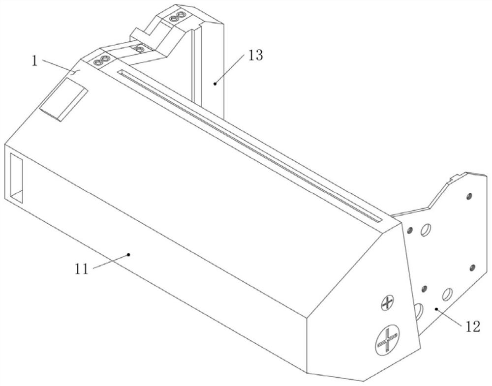
[0032] see Figure 1-9 As shown, the powder chamber connection structure of the split toner cartridge includes:

[0033] Waste toner bin assembly 1, one side of waste toner bin assembly 1 is fixedly installed with toner bin assembly 2, one side of toner bin assembly 2 is fixedly installed with powder discharge knife 9, and the bottom end of powder discharge knife 9 is provided with a magnetic roller 7. An agitator 8 is installed on the inside of the toner bin...


PUM


Abstract

The invention discloses a toner bin connecting structure of a split type toner cartridge. The toner bin connecting structure comprises a waste toner bin assembly, a toner bin assembly is fixedly mounted on one side of the waste toner bin assembly, a toner discharging knife is fixedly mounted on one side of the toner bin assembly, a magnetic roller is arranged at the bottom end of the toner discharging knife, a stirrer is rotatably mounted in the toner bin assembly, a waste toner scraping piece is fixedly installed on one side of the waste toner bin assembly, a photosensitive drum is arranged on one side of the waste toner scraping piece, a charging roller is arranged at the top end of the photosensitive drum, and an installation cover plate is fixedly installed on the front face of the waste toner bin assembly; and the waste toner bin assembly comprises a waste toner bin box, and an elastic limiting plate is integrally formed on one side of the side face of the waste toner bin box. According to the toner bin connecting structure of the split type toner cartridge, a transmission positioning body is designed, traditional complex installation steps are changed, the installation difficulty of the toner cartridge and the toner bin assembly is reduced, the toner bin assembly is convenient to overhaul and clean, and the maintenance speed of the toner cartridge is increased.

Description

technical field [0001] The invention relates to a powder bin connection structure, in particular to a powder bin connection structure of a split toner cartridge, and belongs to the technical field of toner cartridges. Background technique [0002] Toner cartridges, also known as photosensitive drums, generally consist of a base substrate made of aluminum and a photosensitive material coated on the substrate. In laser printers, more than 70% of the imaging components are concentrated in the toner cartridge, and the print quality is actually largely determined by the toner cartridge. [0003] Most of the existing toner cartridges are integral, and with the change of usage needs, there are more and more split toner cartridges, but no matter whether it is an integral toner cartridge or a split toner cartridge, most of the powder bins are fixed, only when adding powder, The toner cartridge needs to be disassembled as a whole. Taking the split type toner cartridge as an example,...

Claims


Application Information

Patent Timeline
Patent Type & Authority Applications(China)
IPC IPC(8): G03G21/16G03G21/18G03G15/08
CPCG03G21/1647G03G21/1671G03G21/1821G03G15/0886
Inventor 苏国林
Owner 珠海天安华泰科技有限公司
Why Eureka
Try Eureka