Target tracking method of photoelectric tracker, terminal and readable storage medium

A technology for photoelectric tracker and target tracking, which is applied to instruments, non-electric variable control, two-dimensional position/channel control, etc. Stable tracking, solving the effect of lag

Active Publication Date: 2022-02-01
成都星宇融科电力电子股份有限公司
View PDF16 Cites 0 Cited by
  • Summary
  • Abstract
  • Description
  • Claims
  • Application Information

AI Technical Summary

Problems solved by technology

[0005] The technical problem to be solved by the present invention is that the traditional photoelectric tracker has low precision and tracking lag, and the purpose is to provide a target tracking method, terminal and readable storage medium of the photoelectric tracker, which solves the real-time tracking problem of the photoelectric tracker

Method used


Image

  • Target tracking method of photoelectric tracker, terminal and readable storage medium
  • Target tracking method of photoelectric tracker, terminal and readable storage medium
  • Target tracking method of photoelectric tracker, terminal and readable storage medium

Examples


Embodiment 1

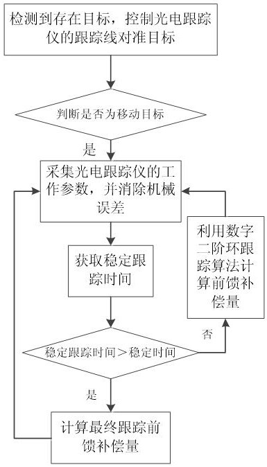
[0082] Such as figure 1 As shown, the present embodiment provides a target tracking method of a photoelectric tracker, including:

[0083] S1. The photoelectric tracker detects that there is a target in the tracking visual area, and obtains the first position of the target, and aligns the tracking line of the photoelectric tracker with the first position;

[0084] Through the existing system of the photoelectric tracker, it is possible to judge whether there is a target to be tracked in the tracking visual area, and mark the position of the target at this time, set it as the first position, and then control the servo of the photoelectric tracker The system aligns the tracking line to the corresponding position.

[0085] S2. Judging whether the target is still at the first position at this time, if it is "no", it is determined that the target is in a moving state, and the tracking line of the photoelectric tracker is controlled to follow the target to move;

[0086] After mov...

Embodiment 2

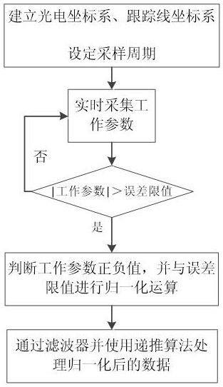
[0098] This embodiment is a specific description of step S3, such as figure 2 shown.

[0099] The method for collecting the working parameters of the photoelectric tracker includes:

[0100] A1. Establish photoelectric coordinate system , tracking line coordinate system ;

[0101] The origin of the photoelectric coordinate system is the intersection of the azimuth rotation axis of the azimuth axis servo system and the pitch rotation axis of the pitch axis servo system, The axis is the direction of the photoelectric tracker when the tracking line is zero, which is parallel to the installation base of the photoelectric tracker. The axis is parallel to the installation base of the photoelectric tracker and perpendicular to axis, pointing to the right along the zero position direction of the trace line, axis perpendicular to the plane ; The azimuth angle is defined by the left-hand rule, and the elevation angle is defined by The plane is zero, and the upward lif...

Embodiment 3

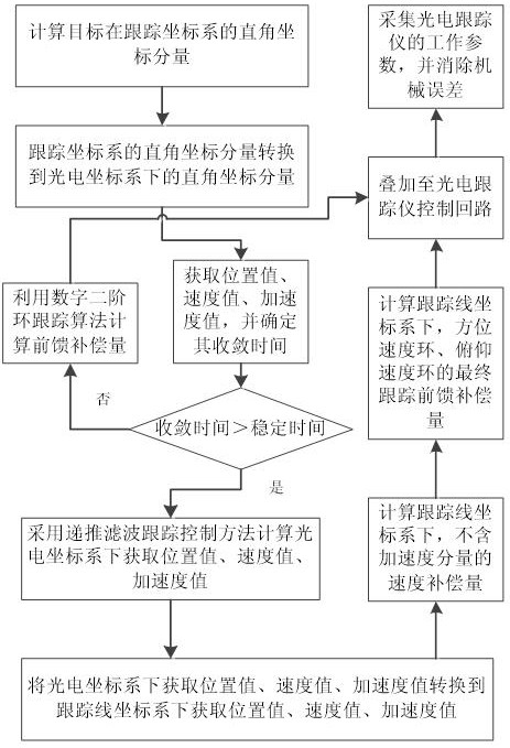
[0124] This embodiment describes steps S4-S6, as image 3 shown.

[0125] The method for obtaining the stable tracking time in step S4 is:

[0126] C1. Calculate the Cartesian coordinate component of the target in the tracking line coordinate system through the tracking deviation of the azimuth, the tracking deviation of the pitch angle and the distance;

[0127] Cartesian coordinate components can be obtained through trigonometric functions, that is, the XYZ values ​​of the target in the tracking line coordinate system.

[0128] C2. Convert the Cartesian coordinate component of the target under the tracking line coordinate system to the photoelectric coordinate system, and obtain the Cartesian coordinate component of the target under the photoelectric coordinate system;

[0129] The photoelectric coordinate system and the tracking line coordinate system have an associated relationship, so those skilled in the art can establish a corresponding conversion matrix according to ...


PUM


Abstract

The invention discloses a target tracking method of a photoelectric tracker, a terminal and a readable storage medium, and belongs to the field of photoelectric detection. The method comprises the steps that it is judged that a target is in a moving state, and a tracking line of the photoelectric tracker is controlled to move along with the target; working parameters of the photoelectric tracker are collected, and mechanical errors in the working process of the photoelectric tracker are eliminated; stable tracking time is obtained, and whether the stable tracking time is greater than set stable time or not is judged; and if yes, the feed-forward compensation amount is calculated through a digital second-order loop tracking algorithm, and if not, the final tracking feed-forward compensation amount is calculated, and tracking of the moving target is executed repeatedly. Mechanical errors caused by mechanical vibration and the like are eliminated, and the data output precision is improved; and then stable tracking time is calculated, the stable tracking time is compared with the stable time, and if the stable tracking time cannot meet the temperature time, the stable tracking time is changed by superposing the feed-forward compensation amount to obtain the final tracking feed-forward compensation amount.

Description

technical field [0001] The invention relates to the field of photoelectric detection, in particular to a target tracking method of a photoelectric tracker, a terminal and a readable storage medium. Background technique [0002] The photoelectric tracker realizes the pointing stability of the tracking line of the photoelectric tracker and the tracking of the target through the azimuth axis servo system and the pitch axis servo system. [0003] The azimuth axis servo system and the pitch axis servo system at the present stage are generally mechanically rotated by tachometers, torque motors, resolvers, etc., thereby changing the azimuth and elevation angles of the photoelectric tracker. problem, there will be mechanical errors. [0004] At the same time, the traditional photoelectric tracker uses the second-order ring tracking method to track the target, which cannot effectively compensate for the disturbance caused by mechanical errors. At the same time, the traditional metho...

Claims


Application Information

Patent Timeline
Patent Type & Authority Applications(China)
IPC IPC(8): G05D1/02G06T7/20
CPCG05D1/0246G06T7/20G05D1/0263G05D1/0223G05D1/0221G05D1/0276
Inventor 何周平柴若愚李书生陈洪才
Owner 成都星宇融科电力电子股份有限公司
Why Eureka
Try Eureka