Target tracking method, terminal, and readable storage medium of a photoelectric tracker
A photoelectric tracker and target tracking technology, which is applied in the direction of instruments, non-electric variable control, two-dimensional position/channel control, etc., can solve the problems of low precision of photoelectric tracker, tracking lag, etc., to improve the accuracy of data output, The effect of eliminating mechanical errors
- Summary
- Abstract
- Description
- Claims
- Application Information
AI Technical Summary
Problems solved by technology
Method used
Image
Examples
Embodiment 1
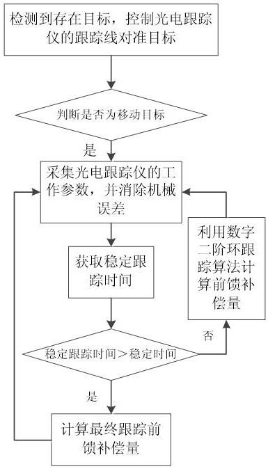
[0084] like figure 1 As shown, the present embodiment provides a target tracking method of a photoelectric tracker, including:
[0085] S1. The photoelectric tracker detects that there is a target in the tracking visual area, and obtains the first position of the target, and aligns the tracking line of the photoelectric tracker with the first position;
[0086] Through the existing system of the photoelectric tracker, it is possible to judge whether there is a target to be tracked in the tracking visual area, and mark the position of the target at this time, set it as the first position, and then control the servo of the photoelectric tracker The system aligns the tracking line to the corresponding position.
[0087] S2. Judging whether the target is still at the first position at this time, if it is "no", it is determined that the target is in a moving state, and the tracking line of the photoelectric tracker is controlled to follow the target to move;
[0088] After moving...
Embodiment 2
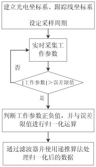
[0100] This embodiment is a specific description of step S3, such as figure 2 shown.
[0101] The method for collecting the working parameters of the photoelectric tracker includes:
[0102] A1. Establish photoelectric coordinate system X g Y g Z g , Tracking line coordinate system X m Y m Z m ;
[0103] The origin O of the photoelectric coordinate system gis the intersection of the azimuth rotation axis of the azimuth axis servo system and the pitch rotation axis of the pitch axis servo system, Y g The axis is the orientation of the photoelectric tracker at the zero position of the tracking line, which is parallel to the installation base of the photoelectric tracker, X g The axis is parallel to the installation base of the photoelectric tracker and perpendicular to Y g Axis, pointing to the right along the zero position direction of the trace line, Z g Axis perpendicular to plane O g x g Y g ;The azimuth angle is defined by the left-hand rule, and the elevatio...
Embodiment 3
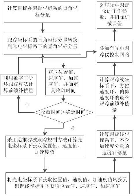
[0129] This embodiment describes steps S4-S6, as image 3 shown.
[0130] The method for obtaining the stable tracking time in step S4 is:
[0131] C1. Calculate the Cartesian coordinate component of the target in the tracking line coordinate system through the tracking deviation of the azimuth, the tracking deviation of the pitch angle and the distance;
[0132] Cartesian coordinate components can be obtained through trigonometric functions, that is, the XYZ values of the target in the tracking line coordinate system.
[0133] C2. Convert the Cartesian coordinate component of the target under the tracking line coordinate system to the photoelectric coordinate system, and obtain the Cartesian coordinate component of the target under the photoelectric coordinate system;
[0134] The photoelectric coordinate system and the tracking line coordinate system have an associated relationship, so those skilled in the art can establish a corresponding conversion matrix according to ...
PUM
 Abstract
Description
Claims
Application Information
 - R&D
- Intellectual Property
- Life Sciences
- Materials
- Tech Scout
- Unparalleled Data Quality
- Higher Quality Content
- 60% Fewer Hallucinations
Browse by: Latest US Patents, China's latest patents, Technical Efficacy Thesaurus, Application Domain, Technology Topic, Popular Technical Reports.
© 2025 PatSnap. All rights reserved.Legal|Privacy policy|Modern Slavery Act Transparency Statement|Sitemap|About US| Contact US: help@patsnap.com


