High-strength multi-stage aluminum alloy bridge

An aluminum alloy, multi-stage technology, applied in the direction of pipe supports, electrical components, pipes/pipe joints/fittings, etc., can solve the problems of cable fixing and cable shunting and export, and meet the requirements of safe use, use and operation. convenient effects

Active Publication Date: 2022-02-01
镇江昌达电气有限公司
View PDF4 Cites 0 Cited by
  • Summary
  • Abstract
  • Description
  • Claims
  • Application Information

AI Technical Summary

Problems solved by technology

[0004] In view of the above situation, in order to overcome the defects of the prior art, the present invention provides a high-strength multi-stage aluminum alloy bridge, which effectively solves the problem that the existing cable bridge can not effectively shunt and lead the cables and can not effectively conduct the cables. fixed problem

Method used


Image

  • High-strength multi-stage aluminum alloy bridge
  • High-strength multi-stage aluminum alloy bridge
  • High-strength multi-stage aluminum alloy bridge

Examples


Embodiment 1

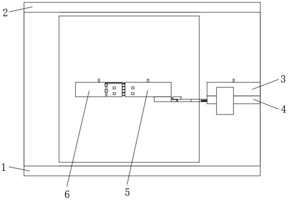
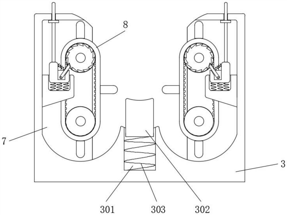
[0033] Embodiment one, by Figure 1 to Figure 3 as well as Figure 7 to Figure 9 Given, the present invention includes a bridge main body 1, the top of the bridge main body 1 is movably installed with a cover plate 2, the bridge main body 1 is a four-way structure bridge structure, and the inside of the bridge main body 1 is equidistantly fixedly installed with a first U-shaped wire-drawing groove 3 , the bottom of the first U-shaped wire holding groove 3 is equipped with a horizontal moving assembly 4, one end of the horizontal moving assembly 4 is installed with a second U-shaped wire holding groove 5, and one end of the second U-shaped wire holding groove 5 is installed with a third U-shaped wire holding groove 6, both sides of the first U-shaped wire holding groove 3, the second U-shaped wire holding groove 5 and the third U-shaped wire holding groove 6 inside are all provided with an adjustment inner cavity 7, and the inner chamber 7 is adjusted. Fixed line components 8 ...

Embodiment 2

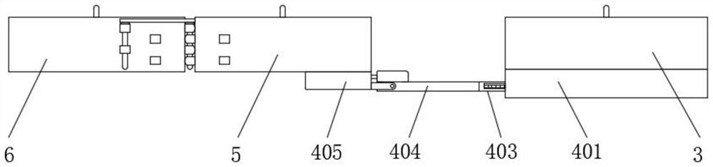
[0035] Embodiment two, on the basis of embodiment one, by figure 2 , Figure 4 to Figure 7 Given, the horizontal movement assembly 4 includes a mounting block 401, the mounting block 401 is fixedly mounted on the bottom of the first U-shaped wire slot 3, one end of the mounting block 401 is provided with a drawing slot 402, and the inside of the drawing slot 402 is movably plugged There is an L-shaped adjustment bar 403, and one end of the L-shaped adjustment bar 403 is equipped with a U-shaped block 404, and an up-and-down rotation adjustment member 405 is connected between the U-shaped block 404 and the second U-shaped line clamping groove 5;

[0036] Both sides of the draw slot 402 are symmetrically provided with a slide groove 9, and one side of the slide groove 9 is provided with a vertical card groove 10, and the inside of the vertical card groove 10 is slidably equipped with a slide block 11, and one side of the slide block 11 is connected to the slide groove. The sec...

Embodiment 3

[0041] Embodiment three, on the basis of embodiment one, by Figure 7 Given, the up and down rotation adjustment member 405 includes a lower groove block 17, the lower groove block 17 is installed at one end of the second U-shaped wire holding groove 5 bottom, and connecting pieces 18 are installed on both sides of the lower groove block 17, both sides Two connecting pieces 18 are rotationally connected with the two ends of the U-shaped block 404, and the top of the lower groove block 17 is provided with an adjustment groove 19, and the inside of the adjustment groove 19 is slidably equipped with a slide bar 20, and one side of the slide bar 20 is connected to the adjustment groove 19. A third spring 21 is installed between the ends;

[0042] A toggle block 22 is installed on the slide bar 20, a taper pin 23 is fixedly installed on one side of the slide bar 20, a riser 24 is installed symmetrically on the top of the U-shaped block 404, and a pair of first Clip 25, a pair of s...


PUM


Abstract

The invention relates to the technical field of cable bridges, and discloses a high-strength multi-stage aluminum alloy bridge which solves the problem that an existing cable bridge cannot effectively shunt and guide out cables and cannot effectively fix the cables. The high-strength multi-stage aluminum alloy bridge comprises a bridge main body, wherein a cover plate is movably mounted at the top of the bridge main body, first U-shaped wire clamping grooves are fixedly formed in the bridge main body at equal intervals, the bottom of each first U-shaped wire clamping groove is provided with a horizontal moving assembly, one end of each horizontal moving assembly is provided with a second U-shaped wire clamping groove, and third U-shaped wire clamping grooves are formed in one ends of the second U-shaped wire clamping grooves. According to the high-strength multi-stage aluminum alloy bridge, a cable can be effectively shunted and led out, and a height difference exists between the shunted and led-out cable and an original position, so that the safety problem caused by cable leading-out contact is solved. Meanwhile, the high-strength multi-stage aluminum alloy bridge is provided with an effective fixing mechanism, so that the cable can be stably clamped and fixed.

Description

technical field [0001] The invention belongs to the technical field of cable bridges, in particular to a high-strength multi-stage aluminum alloy bridge. Background technique [0002] The rigid structural system with close support cables composed of trough-type, tray-type or step-type straight sections, bends, tees, cross components, brackets (arm brackets), hangers, etc. is called a bridge; because buildings A variety of pipelines cross in parallel, and the space is limited, especially in large-scale office buildings, financial commercial buildings, hotels, stadiums and other buildings, where information points are dense. In addition to using floor grooves and buried pipes in walls, cables are laid in shafts and indoor ceilings. Cable trays are widely used in the interior to provide wiring in different directions. Various cables of the weak current system are arranged in the bridge tray according to classification. The best route selection and installation method should be ...

Claims


Application Information

Patent Timeline
Patent Type & Authority Applications(China)
IPC IPC(8): H02G3/04H02G3/06F16L3/06
CPCH02G3/04H02G3/06F16L3/06Y02E10/50
Inventor 郭力嘉
Owner 镇江昌达电气有限公司
Why Eureka
Try Eureka