Supercharge Your Innovation With Domain-Expert AI Agents!

Dispensing and curing device for lens of optical lens

A technology of optical lens and curing device, which is applied to the device for coating liquid on the surface, optics, optical components, etc., which can solve the problems of not having automatic lens feeding, etc., so as to prevent dust, ensure accurate contact surface, and improve work efficiency. efficiency effect

Active Publication Date: 2022-07-15
江西宏欣光学科技有限公司
View PDF7 Cites 0 Cited by
  • Summary
  • Abstract
  • Description
  • Claims
  • Application Information

AI Technical Summary

Problems solved by technology

[0005] In order to overcome the disadvantage that the existing dispensing curing machine does not have the disadvantage of automatically feeding the lens, the purpose of the present invention is to provide a lens of an optical lens that can not only automatically dispense and cure the lens, but also automatically load the lens Curing device with dispensing glue

Method used


Image

  • Dispensing and curing device for lens of optical lens
  • Dispensing and curing device for lens of optical lens
  • Dispensing and curing device for lens of optical lens

Examples


Embodiment 1

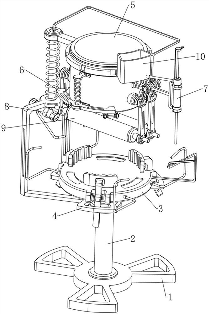
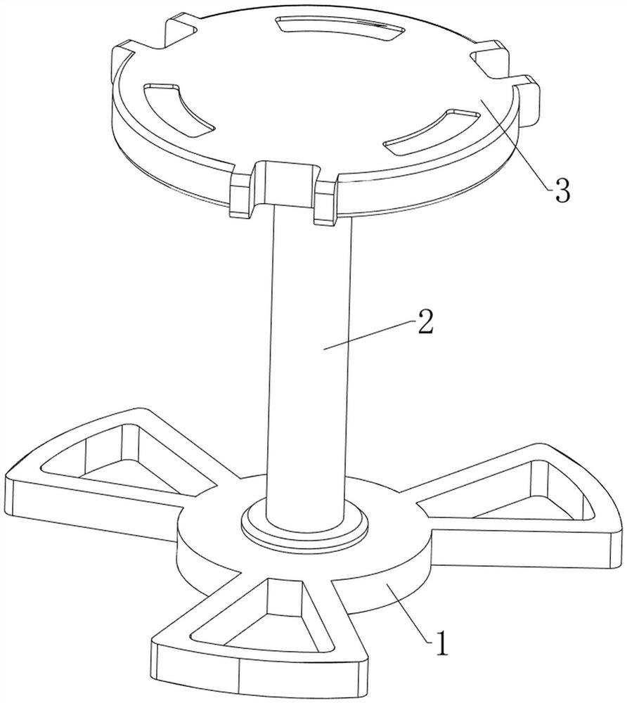
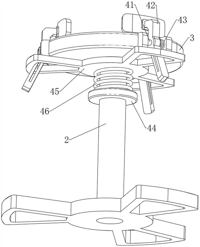
[0038] Dispensing and curing device for lens of optical lens, such as Figure 1-12 As shown, it includes a chassis 1, a fixing rod 2, a feeding tray 3, a positioning mechanism 4, a feeding mechanism 5, a clamping mechanism 6, a dispensing mechanism 7 and a curing mechanism 8, and a fixing rod 2 is welded in the middle of the top of the chassis 1. The top of the fixing rod 2 is provided with a feeding tray 3 for placing the convex lens. The fixing rod 2 is provided with a positioning mechanism 4 for clamping the convex lens. The positioning mechanism 4 is provided with a feeding mechanism 5 for accurately placing the concave mirror. The feeding mechanism 5. The front side is provided with a clamping mechanism 6 for holding the concave mirror, the right side of the feeding mechanism 5 is provided with a dispensing mechanism 7 for dripping glue on the surface of the convex lens, and the left side of the lower part of the feeding mechanism 5 is provided with a convex lens. The cur...

Embodiment 2

[0050] On the basis of Example 1, as figure 1 , Figure 13 , Figure 14 and Figure 15 As shown, it also includes a wiping mechanism 9. The wiping mechanism 9 includes a fifth connecting rod 91, a fifth connecting block 92, a fourth torsion spring 93, a wiping sponge 94, a sixth connecting rod 95 and a guide rod 96. 54 The left and right sides are symmetrically provided with fifth connecting rods 91 in front and back, each fifth connecting rod 91 is provided with a fifth connecting block 92 in a rotatable manner, and four fifth connecting blocks 92 are connected with the fifth connecting rod 91 on the same side. A fourth torsion spring 93 is connected between them, and a sixth connecting rod 95 is rotatably provided on the lower side of the four fifth connecting blocks 92. The wiping sponge 94 for wiping the surface of the convex lens, the left and right sides of the discharge tray 3 are symmetrically provided with guide rods 96 front and rear, and the four sixth connecting...


PUM


Abstract

The invention relates to a glue dispensing and curing device, in particular to a glue dispensing curing device for a lens of an optical lens. The present invention provides a lens dispensing and curing device for an optical lens, which can not only automatically dispense and cure the lens, but also automatically feed the lens. A glue dispensing and curing device for lenses of an optical lens, comprising a chassis, a fixing rod, a feeding tray, a positioning mechanism, etc., a fixing rod is arranged in the middle of the top of the chassis, a feeding tray is arranged on the top of the fixing rod, and the feeding tray is used for placing The convex lens, the fixing rod is provided with a positioning mechanism for fixing. Place the concave mirror in the discharge bucket, and move the discharge bucket downward, so that the glue dispensing mechanism works to drop the glue on the convex lens, and the concave mirror can be bonded to the convex lens. This operation can be performed at the same time, improving work efficiency. In addition, the contact surface between the concave mirror and the convex lens is more accurate, and the amount of glue dripping is the same, and there will be no glue overflow.

Description

technical field [0001] The invention relates to a glue dispensing and curing device, in particular to a glue dispensing curing device for a lens of an optical lens. Background technique [0002] Optical lens is an indispensable component in machine vision system, which directly affects the quality of imaging and the realization and effect of algorithm. In the production process of optical lens, a convex lens and a concave mirror need to be bonded together, then Glue needs to be used. In traditional optical lens processing, glue is manually dispensed on a lens with a glue pen, and then people align the two lenses for bonding. This bonding method cannot guarantee the accurate position of the two lenses. Offset is easy to occur, resulting in inconsistent focus of the lens and affecting the image quality of optical lenses. Now there are many dispensing curing machines on the market. The dispensing curing machine can replace the traditional manual production, which can reduce the...

Claims


Application Information

Patent Timeline
Patent Type & Authority Patents(China)
IPC IPC(8): B05C5/02B05C13/02B05C9/12B05D3/06B08B1/00B05C11/10G02B7/02
CPCB05C5/0208B05C13/02B05C9/12B05D3/067B08B1/006B05C11/10G02B7/025
Inventor 盛军盛浩然毛祉倩王浩宇毛成武
Owner 江西宏欣光学科技有限公司
Features
  • R&D
  • Intellectual Property
  • Life Sciences
  • Materials
  • Tech Scout
  • Unparalleled Data Quality
  • Higher Quality Content
  • 60% Fewer Hallucinations
Learn More