Supercharge Your Innovation With Domain-Expert AI Agents!

Mixing device for producing and processing silicon PU court material

A mixing device and pitch technology, which is applied to the field of mixing devices for the production and processing of silicon PU pitch materials, can solve the problems of hanging on the stirring rod, too many material ratios, inconvenient feeding, etc. residual effect

Pending Publication Date: 2022-02-08
江西向诚新材料有限公司
View PDF1 Cites 0 Cited by
  • Summary
  • Abstract
  • Description
  • Claims
  • Application Information

AI Technical Summary

Problems solved by technology

[0004] The mixing device for the production and processing of silicon PU court materials, when in use, various materials are mixed in proportion to the inside of the device, and the materials are continuously foamed during mixing, which will produce a certain viscosity and adhesion, which is easy inside the device. If it hangs on the stirring rod, after the mixing is finished, the material will concentrate on the structure, resulting in waste. After the material is dry, it is difficult to clean the inside. At the same time, due to the large proportion of materials, when the device is discharging, it is difficult to It is inconvenient to add

Method used


Image

  • Mixing device for producing and processing silicon PU court material
  • Mixing device for producing and processing silicon PU court material
  • Mixing device for producing and processing silicon PU court material

Examples


Embodiment 1

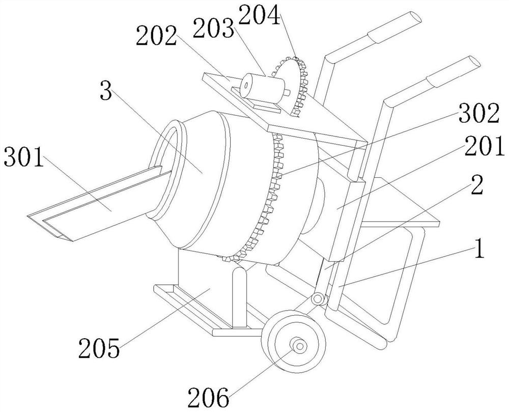
[0032] Embodiment 1: A mixing device for the production and processing of silicon PU court materials, including a support frame 1, the outer surface of the support frame 1 is fixedly connected with a mounting frame 2, and the outer surface of the mounting frame 2 is movably connected with a mixing barrel capable of stirring internal materials 3. A stirring rod 4 is movably connected inside the mixing barrel 3 .

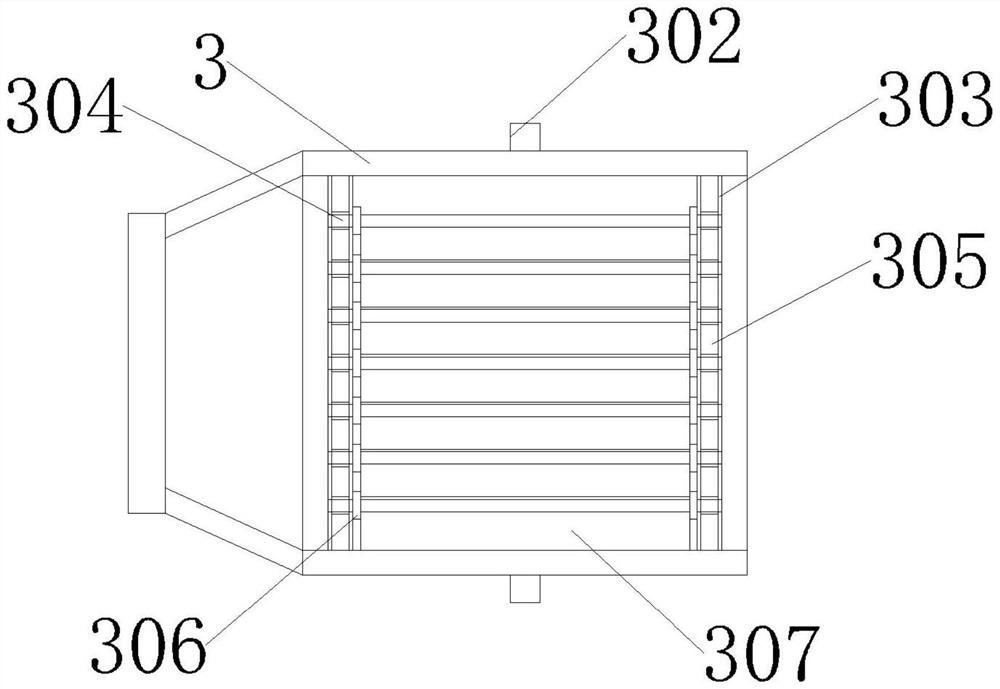
[0033] One side of the mixing barrel 3 is fixedly connected with a discharge hopper 301, the outer surface of the mixing barrel 3 is fixedly connected with a rack 302, and the inner sides of the mixing barrel 3 are fixedly connected with a rotating slideway 303, and the internal movable blocks of the rotating slideway 303 305, the inside of the movable block 305 is fixedly connected with a sleeve ring 308, the inside of the movable block 305 is movably connected with a rotating shaft 304, the middle of the outer surface of the rotating shaft 304 is fixedly connected wi...

Embodiment 2

[0045] Embodiment 2: The difference between Embodiment 2 and Embodiment 1 is that the stirring rod 4 is located at the inner center of the mixing barrel 3 .

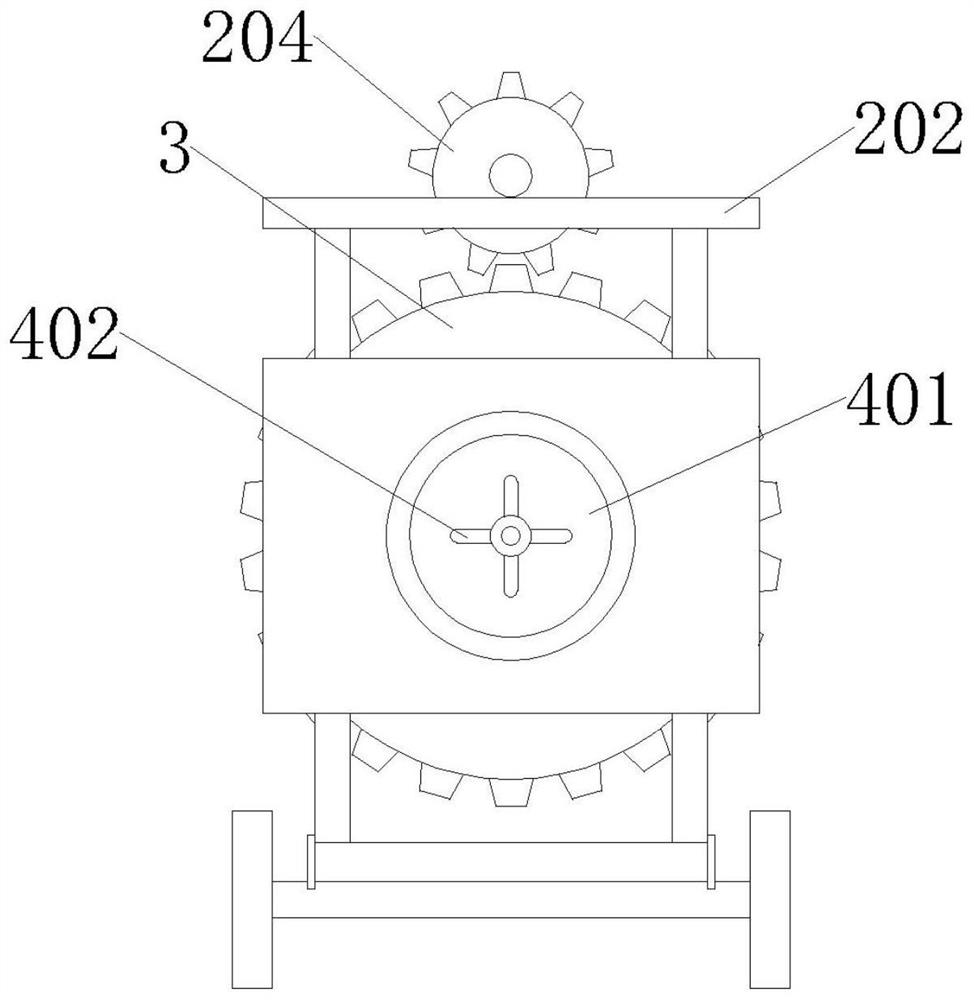
[0046] One side of the stirring rod 4 is fixedly connected with a support frame 405, the top and bottom of the stirring rod 4 are fixedly connected with a material rod 403, one side of the outer surface of the stirring rod 4 is movably connected with a threaded collar 404, and one side of the threaded collar 404 A rotating block 402 is fixedly connected, and a material stopper 401 is fixedly connected to the outer surface of the rotating block 402 .

[0047] The diameter of the material baffle 401 is larger than the diameter of the feed port of the mixing tank 3 , and one side of the material baffle 401 is provided with a silica gel layer.

[0048] One side of the outer surface of the stirring rod 4 is provided with threads, and the threads match the threads of the inner wall of the threaded collar 404 .

[0049] The in...

Embodiment 3

[0052] Embodiment 3: The difference between embodiment 3 and embodiment 2 is that the installation frame 2 is welded to the support frame 1 .

[0053] The outer surface of the mounting frame 2 is fixedly connected with a mounting plate 201, the top of the mounting plate 201 is fixedly connected with a power plate 202, the top of the power plate 202 is fixedly mounted with a motor 203, and the output end of the motor 203 is fixedly connected with a gear 204. The bottom of the support block 205 is rotatably connected with a support block 205, and the two sides of the support block 205 are rotatably connected with moving wheels 206.

[0054] Wherein, the inside of the mounting plate 201 is connected with the feeding port of the mixing tank 3 .

[0055] Wherein, the bottom of the gear 204 meshes with the rack 302 .

[0056] Wherein, the installation frame 2 is connected with the support block 205 through a damping shaft.


PUM


Abstract

The invention provides a mixing device for producing and processing a silicon PU court material. The mixing device comprises a supporting frame, the outer surface of the supporting frame is fixedly connected with a mounting frame, the outer surface of the mounting frame is movably connected with a mixing barrel capable of stirring internal materials, and the interior of the mixing barrel is movably connected with a stirring rod. According to the mixing device for producing and processing the silicon PU court material, through rotation of the mixing barrel, a rotating slide way in the mixing barrel slides, when the rotating slide way moves, moving plates connected with the rotating slide way move to form an included angle, friction is formed between the moving plates in the continuous moving process, and a scraping plate can a scrape material on a friction plate surface, so that the material is prevented from being adhered to a stirring structure during stirring, the device is convenient to clean after being used, excessive residues in the device are prevented, and the material is not prone to waste after being mixed.

Description

technical field [0001] The invention relates to the field of equipment for silicon PU court materials, specifically a mixing device for production and processing of silicon PU court materials. Background technique [0002] Silicon PU material is a kind of strong, durable and tough material, and it still has strong elastic characteristics in a large density range. Overall, it is a very light material, which is easy to be foamed and formed. It is sprayed into various colors, it does not wear and is easy to fold, it is very suitable for the environment of the sports field. However, during construction, the silicon PU material needs to be mixed with multiple materials, and then foamed quickly, while the material is foamed , it will be attached to the inside of the device. [0003] In view of the above-mentioned technical problems of a mixing device for the production and processing of silicon PU court materials, after searching, it was found that there is a patent number 202021...

Claims


Application Information

Patent Timeline
IPC IPC(8): B29B7/10B29B7/16B29B7/24B29B7/26B29B7/80
CPCB29B7/106B29B7/16B29B7/24B29B7/26B29B7/802
Inventor 陈诚
Owner 江西向诚新材料有限公司
Features
  • R&D
  • Intellectual Property
  • Life Sciences
  • Materials
  • Tech Scout
  • Unparalleled Data Quality
  • Higher Quality Content
  • 60% Fewer Hallucinations
Learn More