Unmanned automatic steel coil suspension carrying protection type crane
A crane and suspension technology, applied in the direction of cranes, walking bridge cranes, traveling mechanisms, etc., can solve the problems of shaking of hoisting ropes, unable to ensure the stability of horizontal or vertical movement of steel coils, etc., to prevent steel coils from shaking, preventing shaking effect
- Summary
- Abstract
- Description
- Claims
- Application Information
AI Technical Summary
Problems solved by technology
Method used
Image
Examples
Embodiment 1
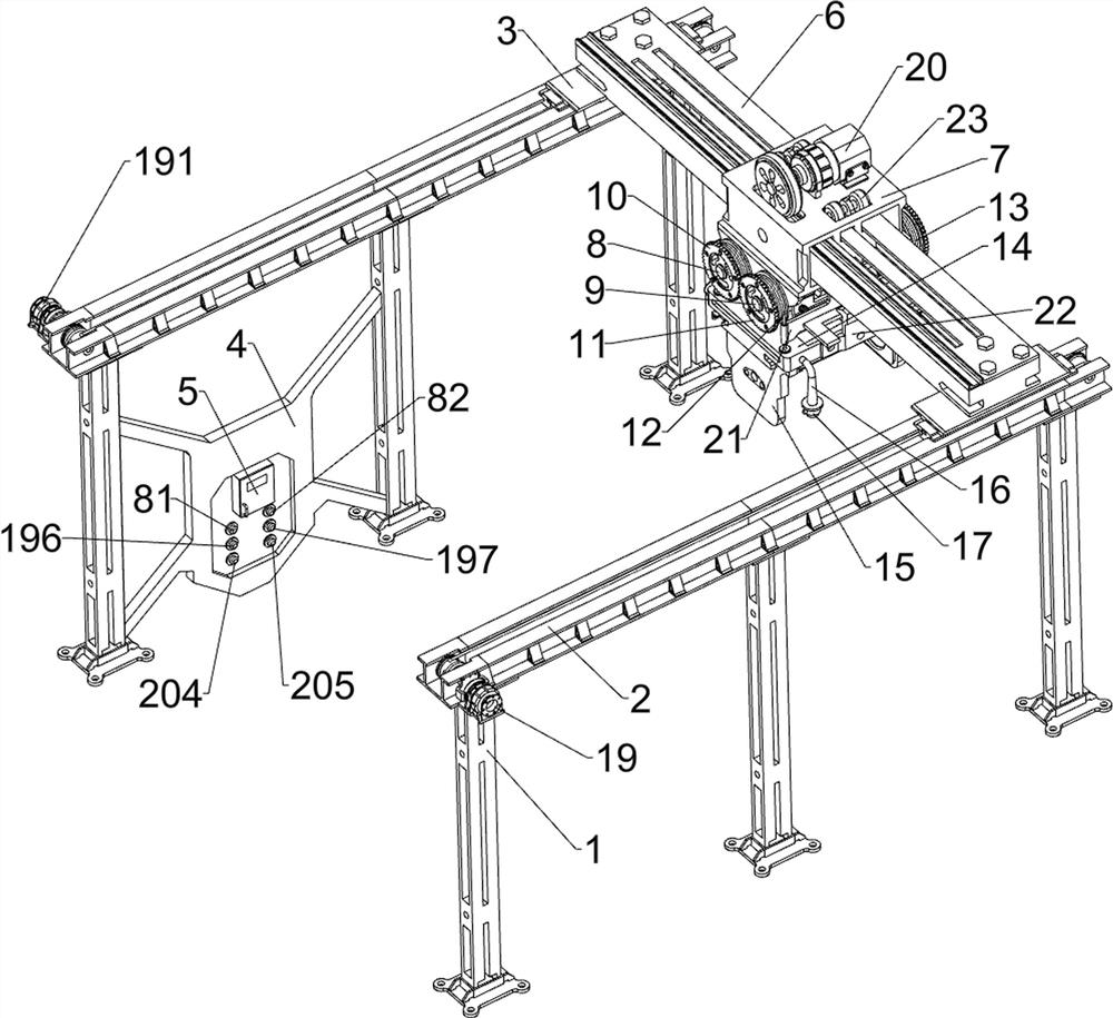
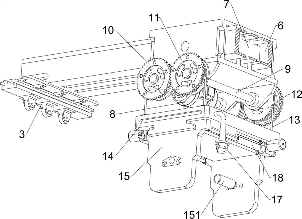
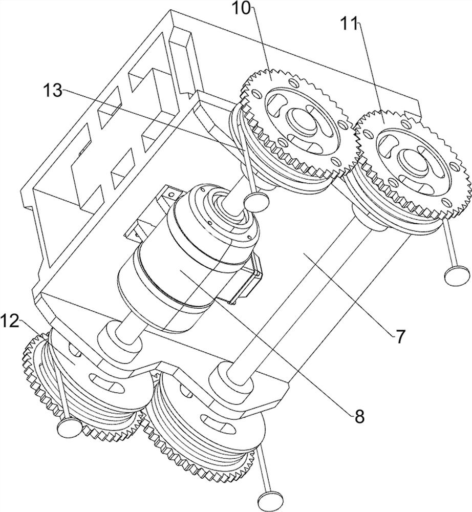
[0039] An unmanned automatic steel coil suspension and handling protective crane, such as figure 1 , figure 2 , image 3 , Figure 13 and Figure 14 As shown, it includes bracket 1, guide rail 2, first slider 3, mounting plate 4, control box 5, slide rail 6, second slider 7, double-axis motor 8, first contact switch 81, second contact switch 82. The first rotating shaft 9, the first transmission gear 10, the second transmission gear 11, the first reel 12, the first steel wire rope 13, the connection block 14, the splint 15, the supporting rod 151, the installation rod 16, the distance sensor 17, Electric push rod 18, lateral movement assembly 19 and longitudinal movement assembly 20, two guide rails 2 are provided, the front and back of the two guide rails 2 are symmetrical, and the bottoms of the two guide rails 2 are connected with three brackets 1 evenly spaced. There is a first slider 3 slidingly connected, a slide rail 6 is connected between the tops of the two first...
Embodiment 2
[0042] On the basis of Example 1, such as figure 1 , Figure 4 and Figure 5As shown, the traverse assembly 19 includes a first reduction motor 191, a second reel 192, a third reel 193, a second wire rope 194, a third wire rope 195, a third contact switch 196 and a fourth contact switch 197 , the left sides of the two guide rails 2 are connected with a first reduction motor 191 by means of bolt connection, the output shaft of the first reduction motor 191 is connected to the guide rail 2 in a rotational manner, and the first reduction motor 191 and the control module are connected through a relay control module connection, the output shafts of the two first reduction motors 191 are connected with a second winding wheel 192, and the two second winding wheels 192 are respectively located in the two guide rails 2, and the right sides in the two guide rails 2 all rotate A third reel 193 is connected in the form, and a second steel wire rope 194 is connected on the two second ree...
Embodiment 3
[0047] On the basis of Example 2, such as figure 1 , Figure 7 and Figure 8 As shown, it also includes a limit assembly 21, the second slider 7 is provided with a limit assembly 21, the limit assembly 21 is used to guide the first steel wire rope 13 and to limit the connection block 14 to prevent the steel coil from shaking. The limit assembly 21 includes a connecting frame 211, a guide sleeve 212 and a limit frame 213. The bottom of the second slider 7 is symmetrically connected with two connecting frames 211 by means of bolt connection. The left and right sides of the two connecting frames 211 are Both are connected with two guide sleeves 212, and the four first steel wire ropes 13 pass through the four guide sleeves 212 respectively. The guide sleeves 212 are used to guide the first steel wire ropes 13 to prevent the steel coil from shaking. A limit frame 213 is connected, and the limit frame 213 engages with the connection block 14, and the limit frame 213 is used to li...
PUM
 Abstract
Description
Claims
Application Information
 - R&D
- Intellectual Property
- Life Sciences
- Materials
- Tech Scout
- Unparalleled Data Quality
- Higher Quality Content
- 60% Fewer Hallucinations
Browse by: Latest US Patents, China's latest patents, Technical Efficacy Thesaurus, Application Domain, Technology Topic, Popular Technical Reports.
© 2025 PatSnap. All rights reserved.Legal|Privacy policy|Modern Slavery Act Transparency Statement|Sitemap|About US| Contact US: help@patsnap.com


