Radiographic detection method for complex steel castings with different thicknesses

A technology for radiographic inspection and steel castings, which is applied in the field of radiographic inspection of thick and complex steel castings, can solve problems such as affecting inspection efficiency and effect, increase in scrap rate, and excessive radiation absorption, so as to improve inspection efficiency and inspection effect, The effect of reducing the formation of waste flakes and equalizing the intensity of rays

Pending Publication Date: 2022-02-08
重庆建工无损检测工程有限公司
View PDF0 Cites 0 Cited by
  • Summary
  • Abstract
  • Description
  • Claims
  • Application Information

AI Technical Summary

Problems solved by technology

The workpiece is manually placed on the detection turntable. The detection process is manually detected. After the detection, whether the workpiece is qualified or not needs to be manually classified. The workload is heavy and the work efficiency is also very low. Due to the different detection positions, X-rays need to be replaced many times. The strength, repeated adjustments also affect the detection time of castings, and the detection time is closely related to the detection proficiency of the operator
[0004] When the complex structures with different thicknesses and thick-walled steel castings are inspected by radiographs, the thickness of the wall absorbs more rays, the exposure to the film is weak, and the photosensitive intensity of the film is weak.
Irregular special inspection workpieces reflect rays to form scattering, which affects the normal exposure of the film, affects the formation of clear images of workpieces to be inspected, and degrades the image recognition of defect parts
The increase of scrap rate will affect the judgment of the test results and affect the detection efficiency and effect

Method used


Image

  • Radiographic detection method for complex steel castings with different thicknesses
  • Radiographic detection method for complex steel castings with different thicknesses
  • Radiographic detection method for complex steel castings with different thicknesses

Examples


Embodiment

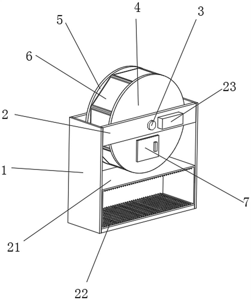
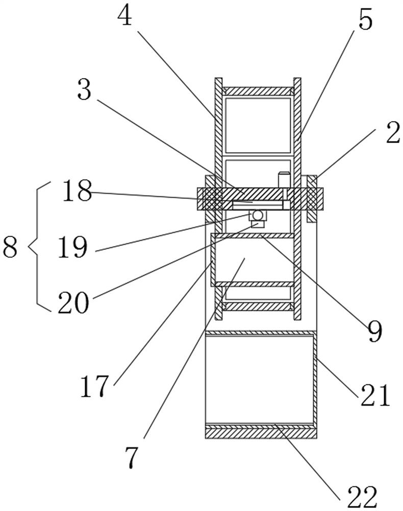
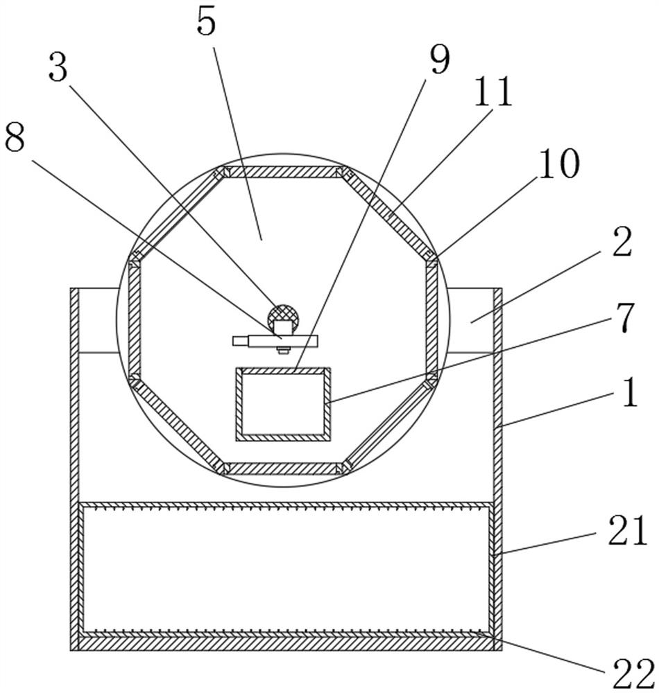
[0039] see Figure 1-4, a ray detection method for complex steel castings with unequal thickness, the method is realized based on a ray detection device for complex steel castings with unequal thickness, the ray detection device for complex steel castings with equal thickness includes a detection frame 1, The front and rear sides of the upper end of the detection frame 1 are provided with installation beams 2, the center of the installation beams 2 on both sides is fixedly connected with the installation shaft 3, the outer surface of the installation shaft 3 is fixedly connected with the fixed end plate 4 near the front end, and the fixed end plate 4 The lower end is provided with a workpiece placement bin 7, the front end of the workpiece placement bin 7 is set through the fixed end plate 4, and the lower end of the middle section of the installation shaft 3 is provided with a radiation transillumination mechanism 8, and the radiation transillumination mechanism 8 is arranged ...


PUM


Abstract

The invention discloses a radiographic detection method for complex steel castings with different thicknesses, and belongs to the technical field of ray detection of the steel castings, the method is realized based on a radiographic detection device for the complex steel castings with different thicknesses, and the radiographic detection device for the complex steel castings with different thicknesses comprises a detection frame, mounting cross beams are arranged on the front side and the rear side of the upper end of the detection frame, a mounting shaft is fixedly connected to the centers of the mounting cross beams on the two sides, and a fixed end plate is fixedly connected to the position, close to the front end, of the outer surface of the mounting shaft.The fixed end plate and the rotating end plate are arranged, and the rotating end plate rotates, so that the imaging film located at the imaging position of the bottom of the workpiece containing bin can be adjusted, continuous transillumination imaging operation can be conveniently conducted, the X-ray incidence position is adjusted for multiple transillumination imaging through the ray transillumination mechanism, and therefore the imaging definition of different positions of the complex steel castings with different thicknesses is guaranteed, and the detection efficiency and the detection effect are greatly improved.

Description

technical field [0001] The invention relates to the technical field of radiation detection of steel castings, in particular to a radiation detection method for complex steel castings with unequal thickness. Background technique [0002] Soon after Mr. Roentgen discovered X-rays, he realized that X-rays could be used for material inspection. But it wasn't until the 1970s that X-rays began to be used in industry. In the process of X-ray inspection, fan-shaped X-rays pass through the sample to be inspected, and then form an enlarged X-ray image on the image receiver (mostly X-ray image intensifiers are used now). The focal area and object distance of x-ray determine the size of the imaging area. Increasing the object distance can increase the imaging area. However, since x-ray is a surface light source, increasing the object distance will also make the image blur. Therefore, the clarity of the image limits the area of ​​X-ray imaging, which directly results in the necessity o...

Claims


Application Information

Patent Timeline
Patent Type & Authority Applications(China)
IPC IPC(8): G01N23/04G01N23/083G01N23/18
CPCG01N23/04G01N23/083G01N23/18
Inventor 赖通邓君安舒洁蒋强唐彬彬
Owner 重庆建工无损检测工程有限公司
Why Eureka
Try Eureka