Three-phase shunt reactor loss test method
A test method and test system technology, applied in the direction of measuring resistance/reactance/impedance, instruments, measuring devices, etc., can solve the problems that three-phase shunt reactors cannot be distinguished and tested, and achieve fast and convenient connection, simple system structure Effect
Pending Publication Date: 2022-02-08
SHANDONG POWER EQUIP
View PDF0 Cites 0 Cited by
- Summary
- Abstract
- Description
- Claims
- Application Information
AI Technical Summary
Problems solved by technology
[0004] In order to solve the above technical problems, the present invention designs a three-phase shunt reactor loss testing method and testing system, using a three-phase intermediate transformer, wherein the three-phase high vo
Method used
View moreImage
Smart ImageViewing Examples
Examples
 PUM
 Abstract
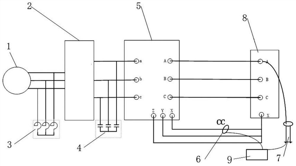
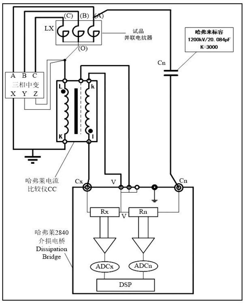
The invention relates to a three-phase shunt reactor loss test method. An intermediate transformer is connected between a power supply and a three-phase intermediate transformer for boosting a system, and a compensation reactor is connected between the power supply and the intermediate transformer for compensating inductive reactive power of the system; a compensation capacitor is connected between the intermediate transformer and the three-phase intermediate transformer and is used for compensating reactive power of the system, and the head and the tail of a high-voltage three-phase winding of the three-phase intermediate transformer are respectively led out; and a current comparator is connected between a three-phase intermediate transformer and a tested three-phase shunt reactor, a standard capacitor is connected to the end part of a sleeve of the tested three-phase shunt reactor, a dielectric loss bridge is connected between the current comparator and the standard capacitor to measure a dielectric loss factor tan delta, and the loss P of the three-phase shunt reactor is calculated, P = U * I * tan delta. The invention also relates to a three-phase shunt reactor loss test system. According to the loss test method and system, the system is simple in structure, rapid and convenient to connect and suitable for loss test requirements of the three-phase shunt reactor.
Description
technical field [0001] The invention belongs to the technical field of transformer testing, and in particular relates to a three-phase shunt reactor loss testing method and system. Background technique [0002] With the development of the power grid, three-phase shunt reactors are widely used in the initial booster station, intermediate contact station and high-voltage direct current transmission converter station of high-voltage long-distance transmission lines. Power transmission capacity, as well as many functions such as suppressing grid resonance overvoltage, preventing generator self-excitation, eliminating no-load long-line capacitance effect and high-voltage cable capacitance effect, suppressing power frequency overvoltage, etc., can save energy and improve the stability and reliability of power system operation . [0003] At present, most of the three-phase shunt reactors use three high-voltage bushings at the first stage, and one neutral point bushing at the end. ...
Claims
Login to View More Application Information
Patent Timeline
 IPC IPC(8): G01R27/02G01R27/26
CPCG01R27/02G01R27/26
Inventor 韩凯谢明德杨在葆李学成马华辉刘中凯席永鹏
Owner SHANDONG POWER EQUIP
- R&D Engineer
- R&D Manager
- IP Professional
- Industry Leading Data Capabilities
- Powerful AI technology
- Patent DNA Extraction
Learn More Browse by: Latest US Patents, China's latest patents, Technical Efficacy Thesaurus, Application Domain, Technology Topic, Popular Technical Reports.
© 2024 PatSnap. All rights reserved.Legal|Privacy policy|Modern Slavery Act Transparency Statement|Sitemap|About US| Contact US: help@patsnap.com


