
Cable joint with fault sensing structure and fault sensing system of cable joint

A cable joint and cable joint technology, applied in cable joints, electrical connection testing and other directions, can solve problems such as partial discharge, high-voltage cable accidents, melting of insulating tape, etc., to facilitate preparation and maintenance, and improve efficiency.

Pending Publication Date: 2022-02-08
江苏依卡维电子科技有限公司
View PDF0 Cites 0 Cited by
  • Summary
  • Abstract
  • Description
  • Claims
  • Application Information

AI Technical Summary

Problems solved by technology

[0003] In the current cable joints, most of the cables in the two cables that need to be connected are butted one by one, wrapped with insulating tape, and then the multiple cables are combined together, and then wrapped with insulating tape in multiple layers. After the cable has a virtual connection and heats up, it is very easy to melt the insulating tape wrapped on the outer layer of the adjacent cable, which will cause a fire and power failure, and there is a certain safety hazard
The electric field stress of the intermediate joint of the power cable is relatively concentrated, which is the weak link of the power cable insulation. It is often easy to cause cable breakdown due to the deterioration of the cable insulation performance, that is, the problem of partial discharge, which is easy to cause high-voltage cable accidents.
In addition, it is impossible to detect and locate the cable joints that cause power outages in real time. During maintenance, multiple cables need to be detected one by one to find the accident point, which is time-consuming and labor-intensive.

Method used


Image

  • Cable joint with fault sensing structure and fault sensing system of cable joint
  • Cable joint with fault sensing structure and fault sensing system of cable joint
  • Cable joint with fault sensing structure and fault sensing system of cable joint

Examples


Embodiment Construction

[0028] The following will clearly and completely describe the technical solutions in the embodiments of the present invention with reference to the accompanying drawings in the embodiments of the present invention. Obviously, the described embodiments are only some, not all, embodiments of the present invention.

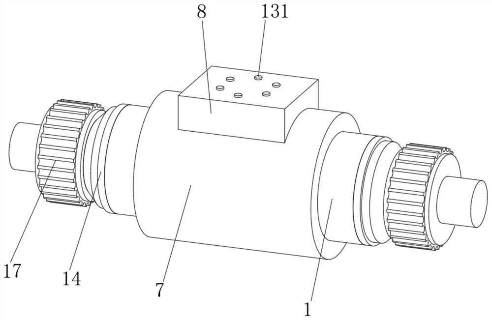
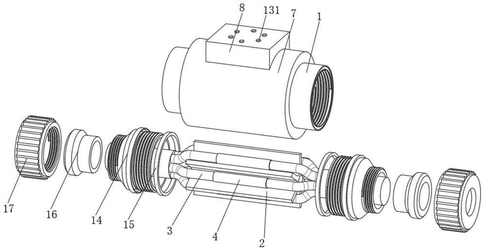
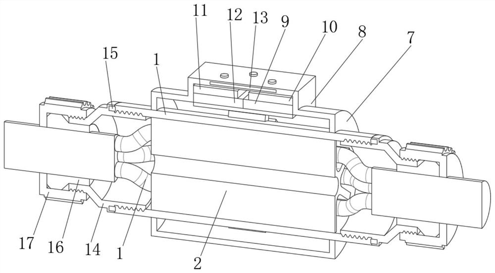
[0029] see Figure 1 to Figure 6, the present invention provides a technical solution: a cable connector with a fault sensing structure, including an inner casing 1, a partition device 2 is placed inside the inner casing 1, a cable connector 3 is placed inside the partition device 2, and the partition device There is a weight-reducing hole in the middle of 2, and there are six partitions symmetrically distributed in the outer center of the partition device 2, which separate the cable joints 3 independently. By setting the partition device 2, the cable joints 3 Separate them one by one to avoid a virtual connection of one cable joint 3. After heating, melt the insulat...


PUM


Abstract

The invention discloses a cable joint with a fault sensing structure and a fault sensing system of the cable joint, and relates to the technical field of cable joints. The cable joint with the fault sensing structure comprises an inner shell, a separation device is arranged in the inner shell, a cable joint body is arranged in the separation device, a temperature sensor and an inductive probe are fixedly mounted in the inner wall of the inner shell, an outer shell is fixedly connected to the exterior of the inner shell, a control box is fixedly connected to the top of the outer shell, and a controller is fixedly mounted in the control box. According to the cable joint with the fault sensing structure and the fault sensing system of the cable joint, the temperature sensor and the sensing probe are arranged outside the cable joint, and the temperature sensor and the sensing probe are used for sensing and detecting the cable joint, the fault type of the cable joint can be conveniently and timely judged, and targeted preparation and maintenance by maintenance personnel are facilitated.

Description

technical field [0001] The invention relates to the technical field of cable joints, in particular to a cable joint with a fault sensing structure and a fault sensing system thereof. Background technique [0002] Cable is a kind of electric energy or signal transmission device, usually composed of several or several groups of wires, cables include power cables, control cables, compensation cables, shielded cables, high temperature cables, computer cables, signal cables, coaxial cables, fire-resistant cables , Marine cables, mining cables, aluminum alloy cables and so on. They are composed of single-strand or multi-strand wires and insulating layers, and are used to connect circuits, electrical appliances, etc. Cables can be divided into DC cables and AC cables according to the photovoltaic power station system. During the operation of the power grid, the cable joint is the weakest link, and about 70% of the cable faults occur at the joint. [0003] In the current cable joi...

Claims


Application Information

Patent Timeline
Patent Type & Authority Applications(China)
IPC IPC(8): G01R31/69H02G15/08
CPCG01R31/69H02G15/08
Inventor 豆桂权夏秋风
Owner 江苏依卡维电子科技有限公司
Learn More