Method for calculating porous medium oil-water two-phase flow based on windward GFDM
A technology of porous media and calculation methods, applied in the directions of calculation, computer-aided design, design optimization/simulation, etc., can solve the problems of difficult windward effect, complex flow field, and difficulty in effectively guaranteeing calculation accuracy.
- Summary
- Abstract
- Description
- Claims
- Application Information
AI Technical Summary
Benefits of technology
Problems solved by technology
Method used
Image
Examples
Embodiment 1
[0045] A multi-hole medium, two-phase flow calculation method based on the wind-winding GFDM, including the following steps:
[0046] S1, establish a two-phase flow model of porous dielectric oil water;
[0047] The two-phase flow model of the porous dielectric oil includes a conservation equation of an oil phase substance, aqueous phase material conservation equation, and auxiliary equation, wherein the two-phase flow of the oil in the porous medium is not interposed.
[0048] Among them, the oil phase substance conservation equation is:
[0049]
[0050] Where: k is permeability, md; k ro = K ro (S w ) Is with aqueous saturation w Relative penetration of oil; μ o Is oil phase viscosity, MPa · S; P o Is oil phase pressure, MPA; Q o It is an oil phase source mesh, 1 / day; T is time, day; o It is an oil phase saturation; φ = φ (p) is a pressure-related reservoir porosity;
[0051] The aqueous phase substance conservation equation is:
[0052]
[0053] In the above formula: k r...
Embodiment 2
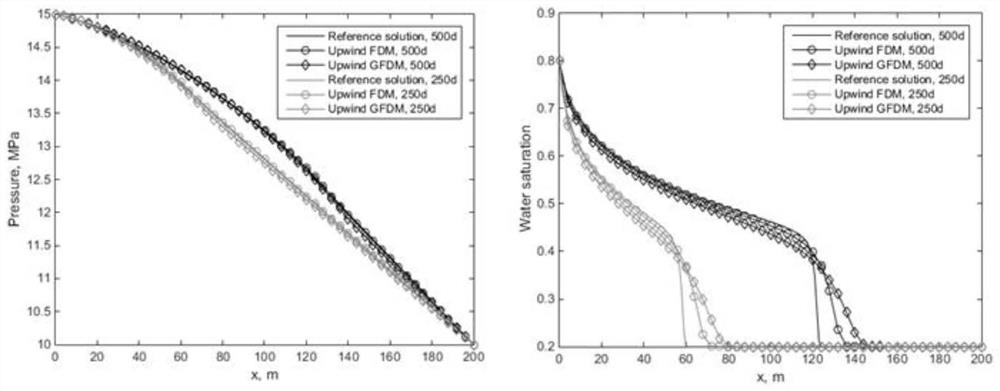
[0101] This embodiment selects a rule of rectangular calculating domain ([0M, 200M] × [0m, 80m]), and the left and right boundary (separately remembering γ) 1 Γ 2 Both are the first type of boundary condition, up and down boundary (separately remembering γ) 3 Γ 4 In order to close the boundary conditions, the source transfer item is 0, Table 1 shows the relevant physical parameters including a phase infiltration expression, the calculation domain initial value, and the specific equation is shown in the equation (13).
[0102]
[0103] p 0 = 10, S w = 0.8,
[0104]
[0105] This embodiment calculates the FDM calculation result obtained by the small spatial step and the small time step (ΔX = 1 M, ΔY = 1m, Δt = 0.005d) as a reference. figure 1 Contrast ΔX = 4m, ΔY = 4M FDM and selection nodes affect domain radius The routing results of the winding GFDM on a one-dimensional line of y = 40m, you can see that the windfx GFDM can get a high precision, especially in the pressure ca...
Embodiment 3
[0115] Example 2 Demonstrates the calculation results of the windfx GFDM to achieve sufficient accuracy, and the node affects the changes in the calculation accuracy. Therefore, compared to the finite difference, finite element or finite volume method, the finite element or finite volume method, etc. The difficulty is greatly reduced.
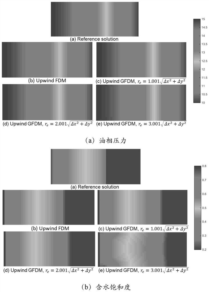
[0116] like image 3 (a), the present embodiment is directed to Example 2, with a more flexible layout method, and no longer a rule of Cartesian cloth point, Figure 4 The calculated saturation and pressure distribution can be seen, and the calculation results can be seen from figure 2 The results in (b) are basically matched, indicating that the inventive GFDM of the present invention can achieve effective calculations in any placement. Then, this example is given image 3 (b) The calculation and distribution points, the initial boundary value condition, and the control equation shown in the same boundary shape, the same as the 3.1 section, only boun...
PUM
 Abstract
Description
Claims
Application Information
 - R&D
- Intellectual Property
- Life Sciences
- Materials
- Tech Scout
- Unparalleled Data Quality
- Higher Quality Content
- 60% Fewer Hallucinations
Browse by: Latest US Patents, China's latest patents, Technical Efficacy Thesaurus, Application Domain, Technology Topic, Popular Technical Reports.
© 2025 PatSnap. All rights reserved.Legal|Privacy policy|Modern Slavery Act Transparency Statement|Sitemap|About US| Contact US: help@patsnap.com


