Voltage control method and device for distributed optical storage system in power distribution network
A voltage control method and technology of an optical storage system, which are applied in circuit devices, AC network voltage adjustment, photovoltaic power generation, etc., can solve problems such as voltage instability in distribution networks, and achieve the effect of solving overvoltage problems and improving stability.
- Summary
- Abstract
- Description
- Claims
- Application Information
AI Technical Summary
Problems solved by technology
Method used
Image
Examples
Embodiment 1
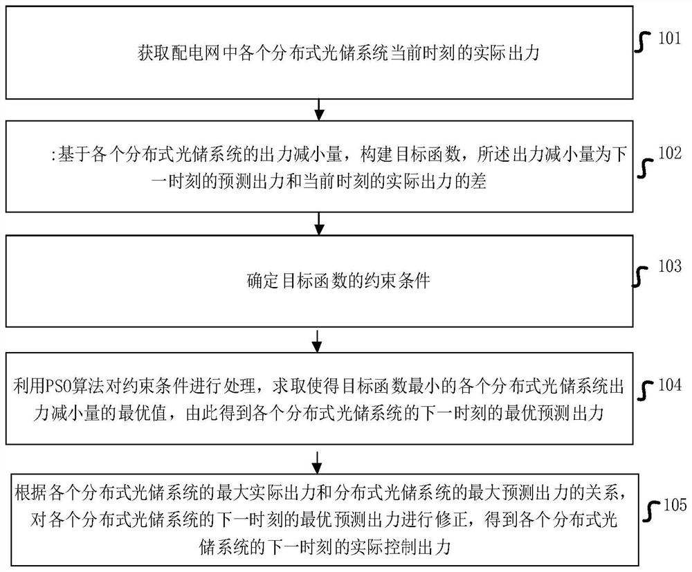
[0062] Such as figure 1 As shown, the embodiment of this application proposes a voltage control method for a distributed optical storage system in a distribution network, including:
[0063] Step 101: Obtain the current actual output of each distributed optical storage system in the distribution network;
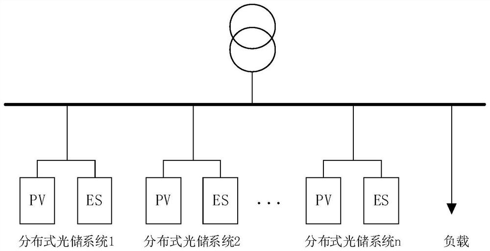
[0064] Such as figure 2 As shown, the distribution network includes n distributed optical-storage systems, and the actual output of the i-th distributed optical-storage system at the current moment is PV stands for Photovoltaic and ES stands for Energy Storage.
[0065] Step 102: construct an objective function based on the output reduction of each distributed optical storage system, the output reduction is the difference between the predicted output at the next moment and the actual output at the current moment;
[0066] The objective function f is:
[0067]
[0068] in, is the output reduction of the i-th distributed optical storage system:
[0069]
[0070]...
Embodiment 2
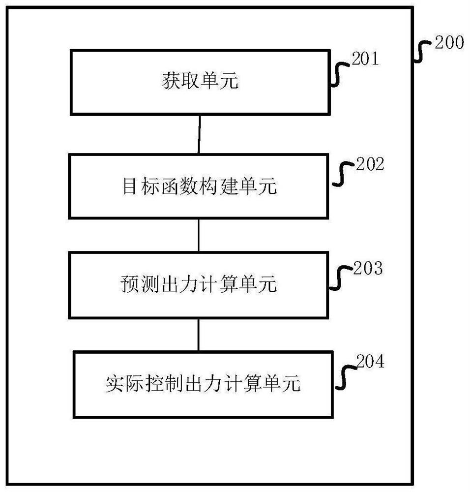
[0101] Based on the above embodiments, this embodiment of the present application provides a voltage control device for a distributed optical storage system in a distribution network, see image 3 As shown, a voltage control device 200 for a distributed optical storage system in a power distribution network provided in an embodiment of the present application at least includes:
[0102] An acquisition unit 201, configured to acquire the actual output of each distributed optical storage system at the current moment;
[0103] The objective function construction unit 202 is configured to construct an objective function based on the output reduction of each distributed optical storage system, and the output reduction is the difference between the predicted output at the next moment and the actual output at the current moment;
[0104] The predicted output calculation unit 203 is used to obtain the optimal value of the output reduction of each distributed optical storage system tha...
Embodiment approach
[0127] As a possible implementation, the node voltage security constraints are:
[0128] u min ≤ U J ≤ U max
[0129] Among them, U J Indicates the voltage of the jth node; U min and U max Respectively represent the lower limit and upper limit of node safety voltage.
[0130] As a possible implementation manner, the actual control output calculation unit 204 is specifically used for:
[0131] Obtain the maximum actual output of the i-th distributed optical storage system
[0132] Obtain the maximum predicted output of the i-th distributed optical storage system
[0133] judge Is it greater than or equal to If yes, the actual control output of the i-th distributed photovoltaic storage system for:
[0134]
[0135] otherwise, Will Output as the output control target of the i-th distributed optical storage system.
PUM
 Abstract
Description
Claims
Application Information
 - R&D
- Intellectual Property
- Life Sciences
- Materials
- Tech Scout
- Unparalleled Data Quality
- Higher Quality Content
- 60% Fewer Hallucinations
Browse by: Latest US Patents, China's latest patents, Technical Efficacy Thesaurus, Application Domain, Technology Topic, Popular Technical Reports.
© 2025 PatSnap. All rights reserved.Legal|Privacy policy|Modern Slavery Act Transparency Statement|Sitemap|About US| Contact US: help@patsnap.com


