
Mini air pump

A technology of micro air pump and pump cover, applied in the direction of pump, pump components, variable displacement pump components, etc., can solve the problems of the change of contact force, the inability of the spring to stand stably, and the inability to ensure the precise operation of the pressure relief valve, etc. Accuracy, the effect of improving stability

Pending Publication Date: 2020-05-19
XIAMEN KOGE MICRO TECH
View PDF0 Cites 0 Cited by
  • Summary
  • Abstract
  • Description
  • Claims
  • Application Information

AI Technical Summary

Problems solved by technology

[0003] In the micro-air pump with integrated pump and valve in the related art, the pressure relief airflow will flow into the spring chamber and directly beat on the spring. The spring cannot stand stably in the spring chamber due to the influence of the air pressure, which will cause the spring to resist the pressure relief valve. The relay will change, and the pressure relief valve cannot be guaranteed to operate accurately under the predetermined air pressure conditions
[0004] In addition, if the pressure relief airflow is directly discharged into the atmosphere, it is easy to generate the sound of airflow, which will increase the working noise of the micro air pump to a certain extent.

Method used


Image

  • Mini air pump
  • Mini air pump
  • Mini air pump

Examples


Embodiment Construction

[0034] Embodiments of the present invention are described in detail below, and examples of the embodiments are shown in the drawings, wherein the same or similar reference numerals denote the same or similar elements or elements having the same or similar functions throughout. The embodiments described below by referring to the figures are exemplary and are intended to explain the present invention and should not be construed as limiting the present invention.

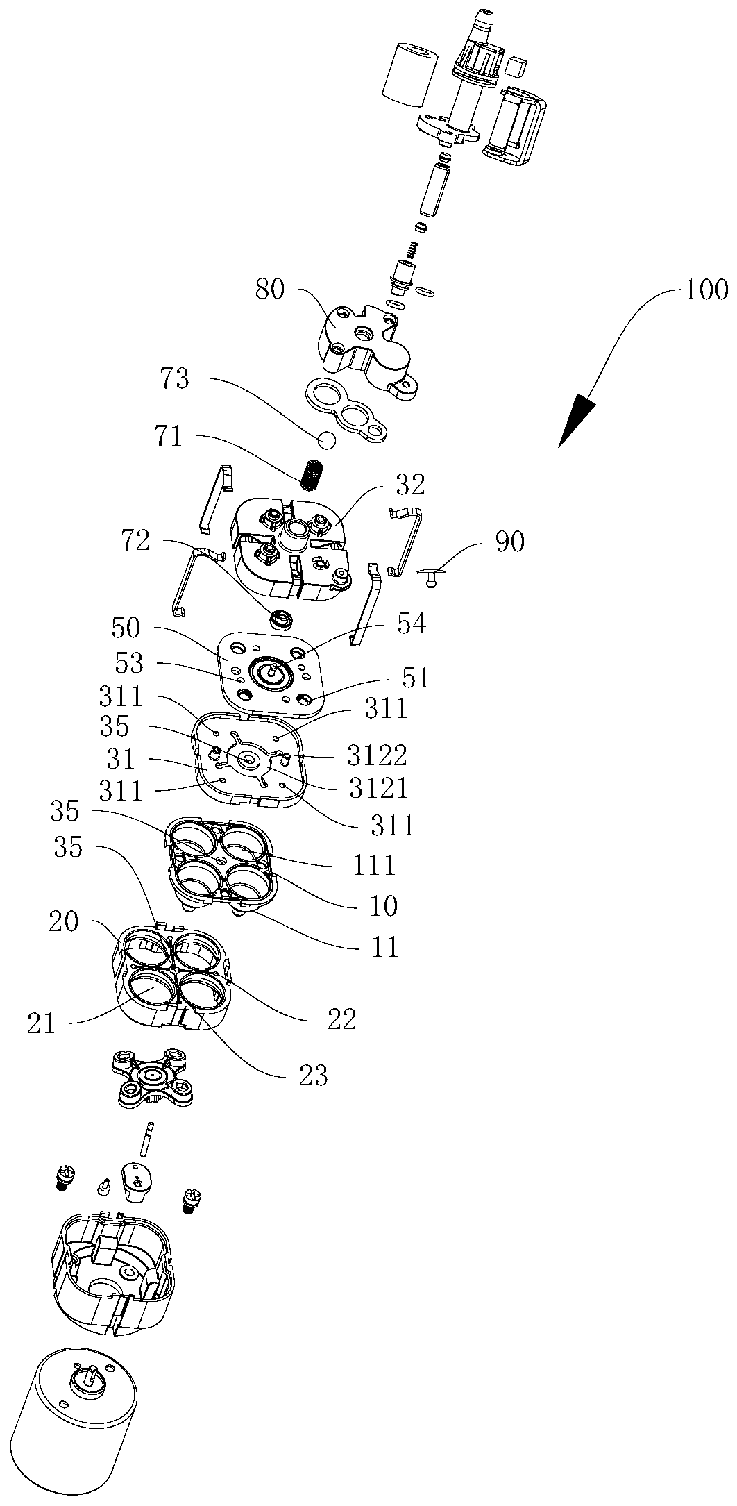
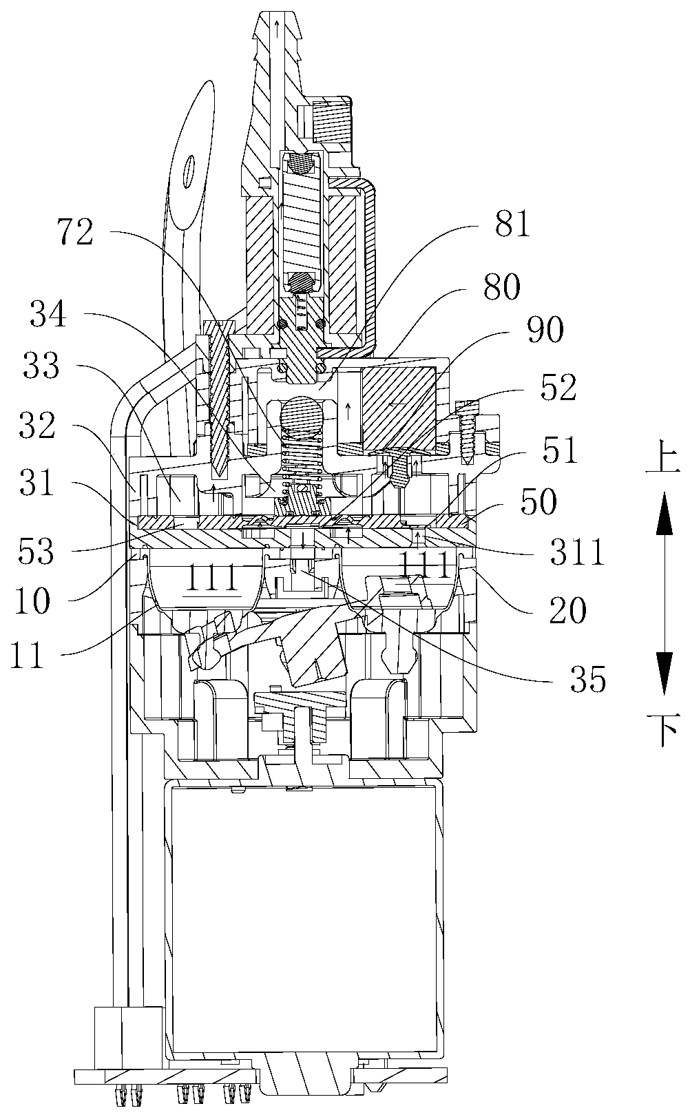
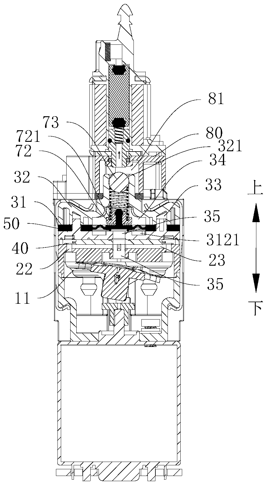
[0035] Refer below Figure 1-Figure 3 , describes the micro air pump 100 according to the embodiment of the present invention.

[0036] The micro air pump 100 includes a diaphragm 10, a bag seat 20, a pump body, an inlet valve 40, an outlet valve 51, a pressure relief valve 52 and a pre-compression assembly.

[0037] Such as figure 1 combine figure 2 and image 3 As shown, one side of the diaphragm 10 (as figure 2 The lower side of the middle) has a plurality of capsules 11, and the capsules 11 are constructed t...


PUM


Abstract

The invention discloses a mini air pump. The mini air pump comprises a membrane, a bag seat, a pump body, an air inlet valve, an air outlet valve, a pressure relief valve and a pre-pressing assembly,wherein the bag seat is provided with a plurality of bag ports penetrating through the bag seat in the thickness direction; the membrane is attached to the bag seat, a plurality of bag bodies penetrate through the bag ports correspondingly, and the bag seat is provided with an air inlet channel; the pump body comprises a valve seat and a pump cover which are overlapped, the valve seat is overlapped on the membrane, and an air outlet cavity and a spring cavity which are independent of each other are formed by the valve seat and the pump cover; the valve seat is provided with an air outlet channel, and the air outlet channel communicates with bag cavities; the valve seat, the membrane and the bag seat are all provided with return channels communicating with each other; the return channels communicate with the air inlet channel and does not communicate with the spring cavity; and the pre-pressing assembly is arranged in the spring cavity and comprises a spring, and the spring applies pre-pressure to the pressure relief valve. The mini air pump provided by the embodiment of the invention has the advantages that the action accuracy of the pressure relief valve is high, and a device to be inflated is pressurized stably.

Description

[0001] This application is based on "Chinese patent applications with application numbers 201911280686.3 and 201922241927.5, and claims the priority of the above-mentioned patent applications. The entire content of the above-mentioned patent applications is hereby incorporated by reference into this application. technical field [0002] The invention relates to the technical field of pumps, in particular to a micro air pump. Background technique [0003] In the micro-air pump with integrated pump and valve in the related art, the pressure relief airflow will flow into the spring chamber and directly beat on the spring. The spring cannot stand stably in the spring chamber due to the influence of the air pressure, which will cause the spring to resist the pressure relief valve. The relay will vary, and there is no guarantee that the pressure relief valve will operate accurately under the predetermined air pressure conditions. [0004] In addition, if the depressurized airflow ...

Claims


Application Information

Patent Timeline
Patent Type & Authority Applications(China)
IPC IPC(8): F04B45/04F04B39/00F04B39/10F04B39/12
CPCF04B39/0055F04B45/04F04B39/10F04B39/123
Inventor 许清香
Owner XIAMEN KOGE MICRO TECH
Learn More