Integrated separator

A separator and static separation technology, applied in the separation method, solid separation, dispersed particle separation, etc., can solve the problem of the overall layout height of the cement plant of the separator and the huge construction cost, and achieve the effect of minimizing the building height

Pending Publication Date: 2022-02-08
F L SMIDTH & CO AS
View PDF11 Cites 0 Cited by
  • Summary
  • Abstract
  • Description
  • Claims
  • Application Information

AI Technical Summary

Problems solved by technology

In both cases, the height of the overall layout of the cement plant where the separator is arranged is costly due to the high construction costs

Method used


Image

  • Integrated separator
  • Integrated separator
  • Integrated separator

Examples


Embodiment Construction

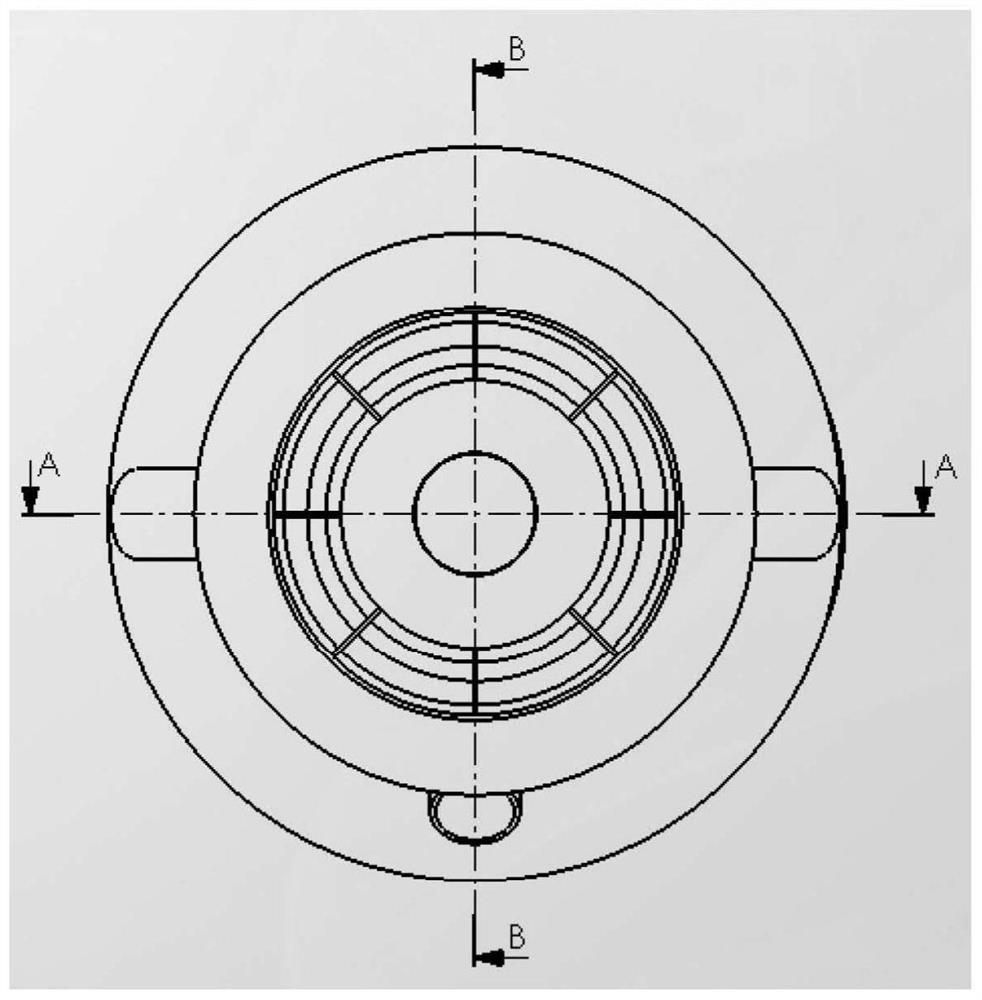
[0035] figure 1 The integrated separator according to the invention is schematically shown from a top view, showing a feed chute, a waste chute and a housing with a retaining rod for holding a frustum of a cone.

[0036] figure 2 The frustum of the cone according to the invention is schematically shown from a top view, and how the frustum of the cone is held in its position by the holding rod.

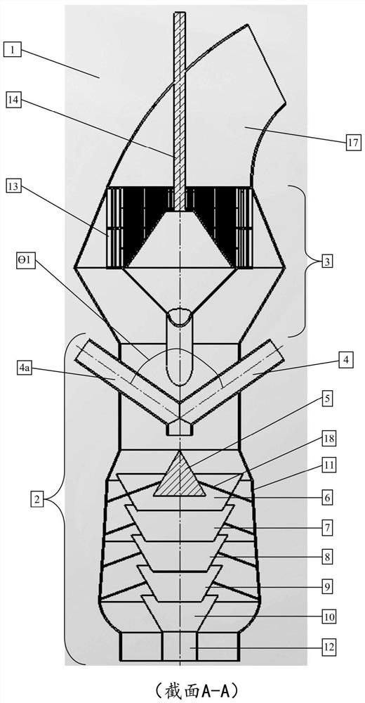
[0037] image 3 An integrated separator 1 for separating coarse and fine particles in a cement manufacturing process is schematically shown. Integrated separator 1 includes:

[0038] - static separator 2,

[0039] - a dynamic separator 3 arranged in an uppermost position relative to the static separator 2, and

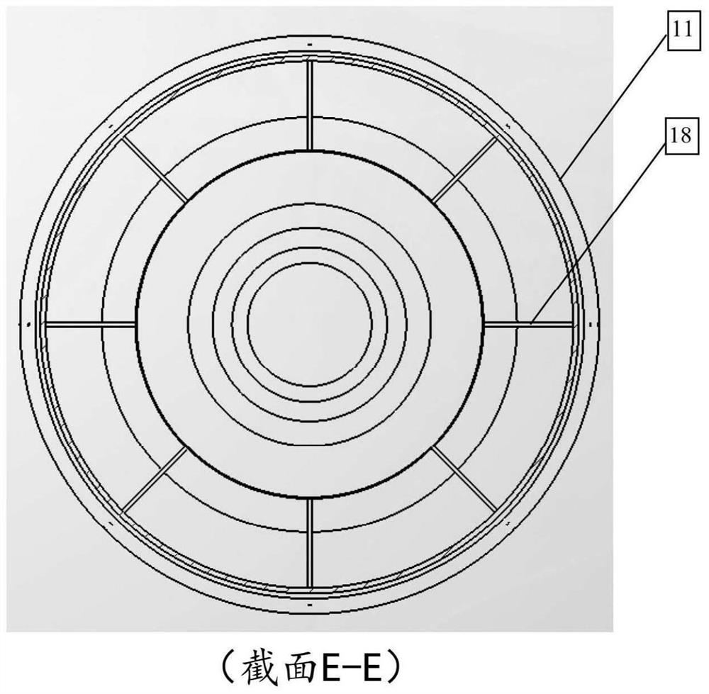
[0040] The static separator 2 comprises a housing 11 , a defocusing cone 5 and a first inverted frustum cone 6 . The defocusing cone 5 is arranged adjacent to the first inverted frustum 6 by means of a holding rod 18 . A holding rod 18 is connected to the first inverted...


PUM


Abstract

The invention relates to an integrated separator (1) for separating coarse and fine particles in a cement making process, said integrated separator (1) comprising a static separator (2) and dynamic separator (3), said dynamic separator (3) being arranged in an uppermost position relative to said static separator (2) and said static separator (2) comprising an outer housing (11); a de-agglomeration cone (5) and a first inverted frustum cone (6), said de-agglomeration cone [5] arranged adjacent to said first inverted frustum cone (6) by holding rods (18), said holding rods (18) are connected to said inverted first frustum of cone (6).

Description

technical field [0001] The present invention relates to an apparatus and method for an integrated separator in a cement plant. Background technique [0002] In the cement industry, separators are used to separate coarse and fine particles from the feed. According to the working principle, the separator is mainly divided into static and dynamic separators. As the name implies, static separators are constructed of non-moving parts, while dynamic separators include internal moving parts. There are two main areas where separators are used in cement plants: the first is in the coarse grinding area and the other is in the fine grinding area. In both cases, the height of the overall layout of the cement plant in which the separator is arranged is expensive due to the high construction costs. [0003] Therefore, it would be advantageous to be able to apply a separator that would reduce the height of the cement plant where the separator is located, thereby reducing the constructio...

Claims


Application Information

Patent Timeline
Patent Type & Authority Applications(China)
IPC IPC(8): B01D45/02B07B7/04B07B7/083B07B9/02
CPCB01D45/02B07B7/04B07B9/02B07B7/083B07B7/086B07B7/10
Inventor M.纳图杜赖A.M.P.阿帕杜赖
Owner F L SMIDTH & CO AS
Why Eureka
Try Eureka