exhaust gas turbocharger

An exhaust gas turbine and supercharger technology, which is applied in gas turbine installations, machines/engines, engine functions, etc., can solve the problems of reducing the efficiency of exhaust gas turbochargers, reducing turbine efficiency, etc., to improve response behavior, reduce noise, use Life extension effect

Active Publication Date: 2018-06-15
BMTS TECH SHANGHAI CO LTD
View PDF5 Cites 0 Cited by
  • Summary
  • Abstract
  • Description
  • Claims
  • Application Information

AI Technical Summary

Problems solved by technology

However, this has the effect that exhaust gases can flow behind the turbine blades, thus reducing the efficiency of the turbine
This reduces the efficiency of the exhaust gas turbocharger

Method used


Image

  • exhaust gas turbocharger
  • exhaust gas turbocharger
  • exhaust gas turbocharger

Examples


Embodiment Construction

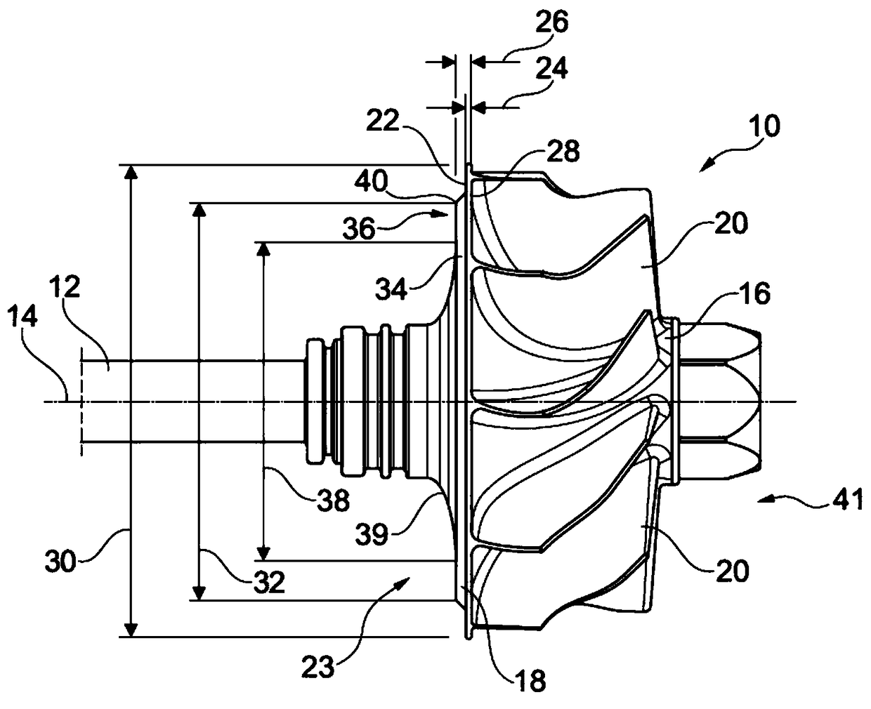
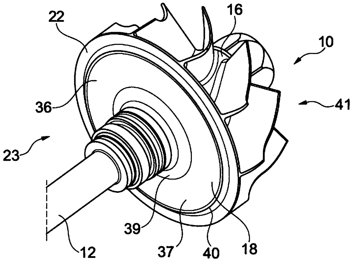
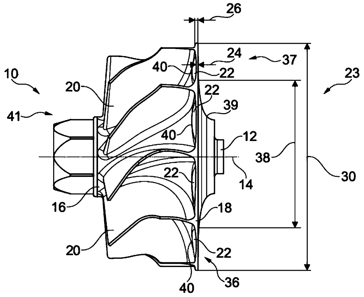
[0029] A turbocharger (not shown) comprises a turbine 10 fixedly connected in rotation via a shaft 12 to a compressor wheel (not shown) mounted rotatably about an axis of rotation 14 and driven by exhaust gas vapor . The turbine 10 has a hub 16 , a wheel backing 18 , and a plurality of blades 20 extending radially outward from the hub 16 on a flow side 41 and axially from the wheel backing 18 . Thus, the blades 20 extend in the region where the hub 16 and the wheel backing 18 turn. In this respect, the blades 20 are curved in such a way that flow energy from the exhaust gas vapor can be converted into a rotational movement of the turbine 10 caused by the blades 20 . As a result, the turbine 10 and thus also the compressor wheel of the exhaust gas turbocharger can be driven by the exhaust gas vapor. No blades 20 are arranged on the rear side 23 of the wheel backing 18 facing away from the flow, so that the rear side 23 has a low resistance to flow.

[0030] In order to reduc...


PUM


Abstract

The invention relates to an exhaust gas turbocharger having a turbine (10) fixedly connected in rotation to a compressor wheel via a shaft (12), said turbine (10) having a hub (16), a disc-shaped A wheel backing (18) and a plurality of blades (20) extending radially from the hub (16) and axially from the wheel backing (18). In this respect, the essence of the invention is that the wheel backing (18) of said turbine (10) comprises at least one reduced region (22) of reduced axial thickness (24).

Description

technical field [0001] The invention relates to an exhaust gas turbocharger having a turbine fixedly connected in rotation via a shaft to a compressor wheel, the turbine having a hub, a disk-shaped wheel backing and a plurality of blades extending from the hub diameter extends axially from the wheel backing. Background technique [0002] In automotive sector gears, this tapered term is used to reduce losses in the internal combustion engine. In this respect, the swept volume of the internal combustion engine is reduced and an additional supercharging device, such as an exhaust gas turbocharger, is used to achieve the required power. The efficiency of the internal combustion engine can thus be improved on account of reduced throttling and friction losses. However, exhaust gas turbochargers exhibit a relatively poor response behavior, especially at low rotational speeds of the internal combustion engine, which is often referred to as turbo lag. During low power events, such...

Claims


Application Information

Patent Timeline
Patent Type & Authority Patents(China)
IPC IPC(8): F01D5/04F01D5/14F01D5/28F02C6/12
CPCF01D5/04F01D5/141F01D5/147F01D5/28F02C6/12F05D2300/182F01D5/027F01D5/048F05D2220/40F05D2300/174F01D5/12F04D29/284F05D2240/60F05D2260/96
Inventor 托马斯·施特里德尔迈尔约亨·施拉耶
Owner BMTS TECH SHANGHAI CO LTD
Why Eureka
Try Eureka