Inverter-charger combination

a technology of inverter and charger, which is applied in the direction of charging stations, battery/fuel cell control arrangements, transportation and packaging, etc., can solve the problems of inability to meet the current industry requirements for charging efficiency and the majority of the onboard battery power of electric vehicles, so as to reduce the number of gate drivers, optimize motor performance, and reduce the inductance and impedance of gate drivers

Active Publication Date: 2019-04-02
CURRENT WAYS
View PDF5 Cites 0 Cited by
  • Summary
  • Abstract
  • Description
  • Claims
  • Application Information

AI Technical Summary

Benefits of technology

[0010]In one aspect, the invention combines the functions of powering a load and charging a rechargeable energy storage system (RESS) into a single device without compromising efficiency. In an electric vehicle application, a device according to the invention fulfills the requirements of the traction inverter, namely, higher currents for vehicle propulsion and lower switching frequencies, with the requirements of the charger, namely, lower currents for charging and higher switching frequency. The topology in an inverter-charger combination according to the invention enables optimal operation of both functions.

Problems solved by technology

These inverters are typically called “traction inverters” and consume most of the onboard battery power of the electric vehicle.
Past attempts at combining inverting and charging in a single device have proven that traction inverter and charger can be combined but either at the expense of charging efficiency or of costly methods involving the use of the traction motors with a winding inductance that interacts with the AC electrical power grid.
Attempts to use the same semiconductors that drive the electric motor to convert the AC power and voltage from the electric utility grid and charge the battery have proven that semiconductor losses, particularly switching losses—those losses incurred in the states between the off and on states and the on and off states of the semiconductor—are sufficiently high to make charging efficiency unacceptable under present industry requirements.

Method used


Image

  • Inverter-charger combination
  • Inverter-charger combination
  • Inverter-charger combination

Examples


first embodiment

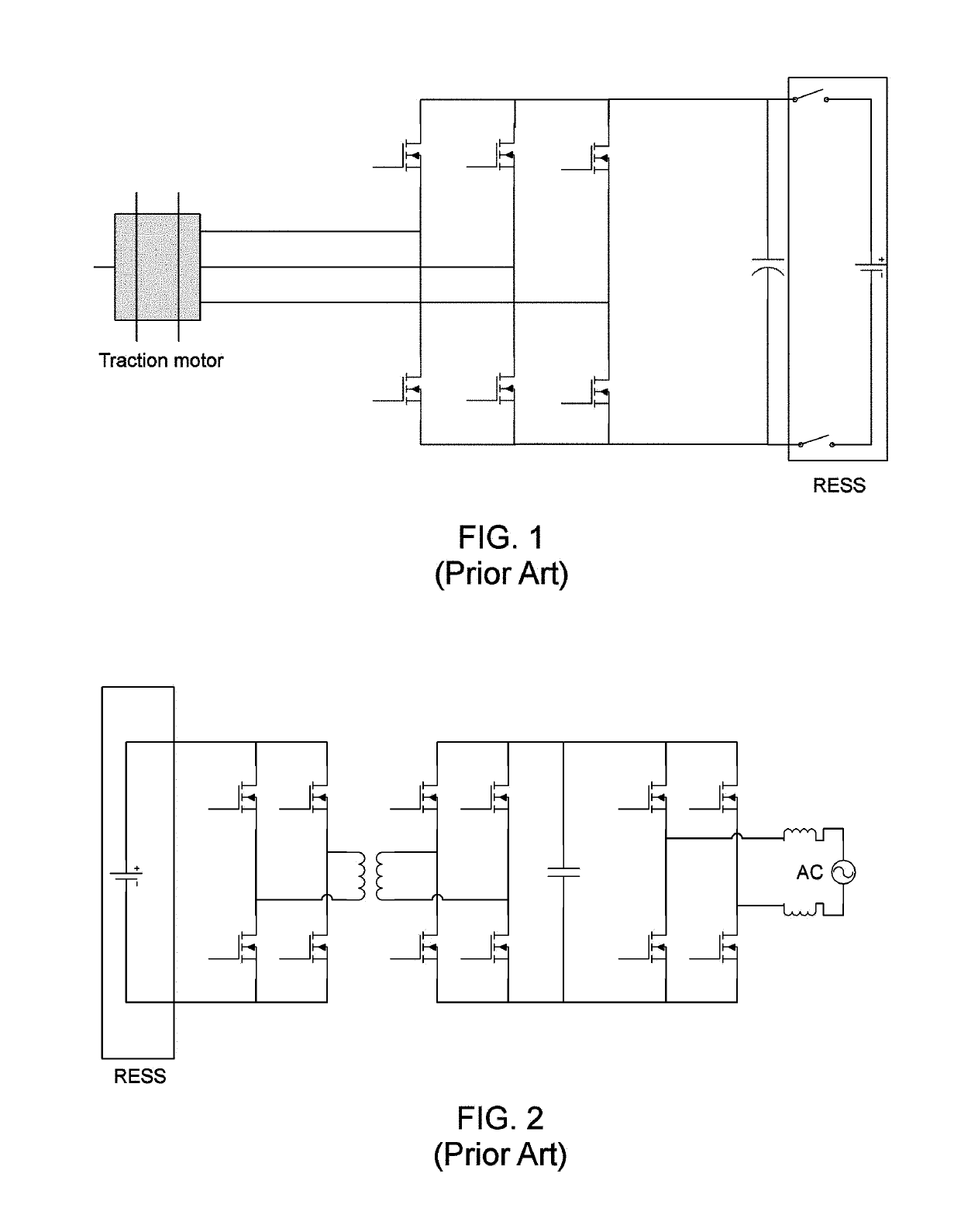
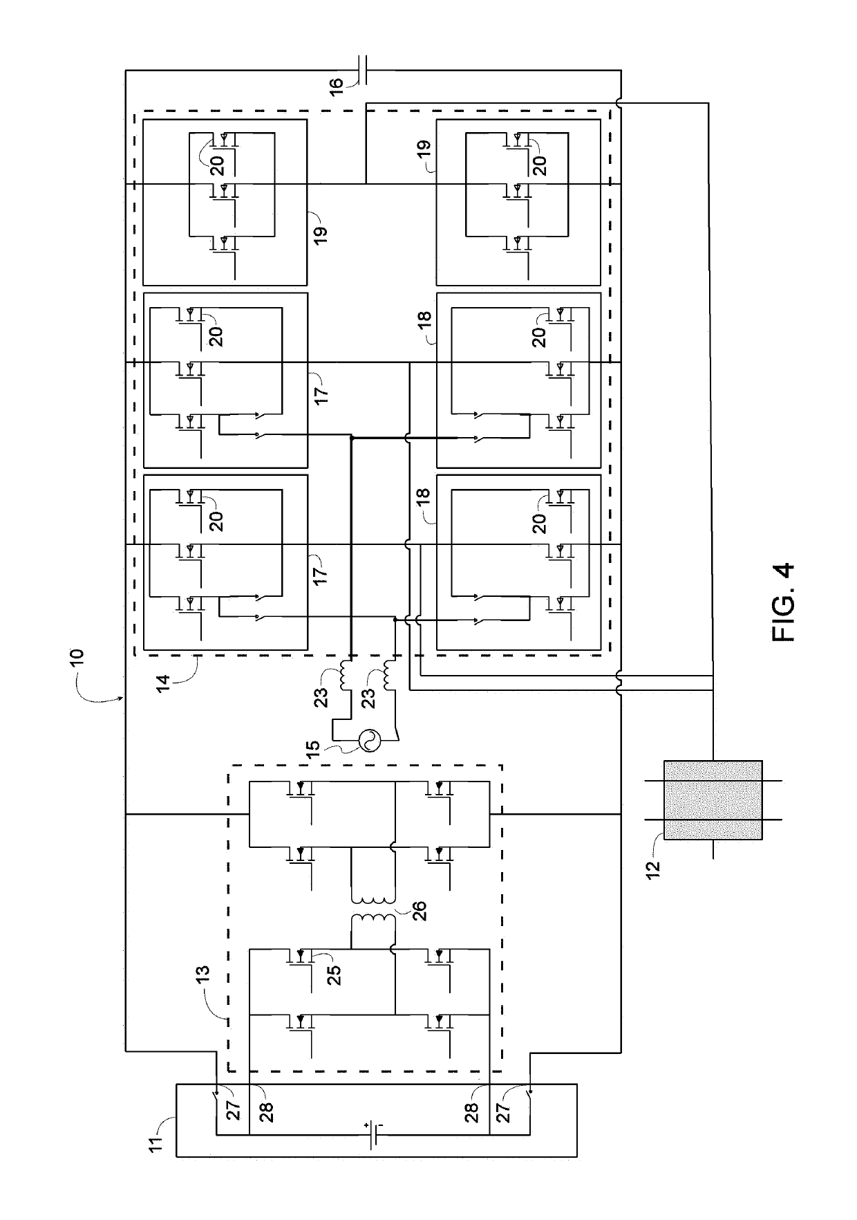
[0035]FIG. 4 illustrates an inverter-charger combination 10 according to the invention, which is operatively coupled to a rechargeable energy storage system (RESS) 11 at one end and to a load 12 at another end. In one example of use, RESS 1 is a battery and load 12 is a traction motor of an electric vehicle. This embodiment is adapted for single phase charging, as will be discussed in greater detail later.

[0036]The basic components of inverter-charger combination 10 include a dual active bridge 13, a plurality of switching elements 14.

[0037]Dual active bridge 13 provides galvanic isolation to RESS 11 and comprises a plurality of RESS-side switches 25 and a dual active bridge transformer 26. As shown in FIG. 4, dual active bridge 13 is interposed between the plurality of switching elements 14 and is connected in parallel with plurality of switching elements 14 and with capacitor 16, which operates as a direct current (DC) link capacitor. RESS 11 is connected to inverter-charger combi...

second embodiment

[0050]An inverter-charger combination according to this second embodiment may be used for three-phase charging of a RESS above 19.2 kW, and, more typically, may be used for three-phase charging of a RESS above 10 kW.

[0051]As it can be seen, in an inverter-charger combination according to the invention, the use of the traction inverter and the charger are mutually exclusive so the same processor can be used to control both functions, reducing costs. Moreover, the same DC link structures can be used for both functions, also reducing costs.

[0052]It can also be seen that, in an electric vehicle, by deploying a highly efficient DC-DC converter with sufficient current to deliver DC current to the traction inverter, a constant or variable DC link voltage strategy can be developed that optimizes motor performance irrespective of the state of charge of the battery of the vehicle.

[0053]While the preceding two embodiments include six switching elements 17, 18, or 19, it should be understood th...


PUM


Abstract

An inverter-charger combination includes plurality of first and second switching elements, a capacitor, and a dual active bridge, connected in parallel to one another. The first and the second switching elements are connected in series to form switching subassemblies that are disposed in parallel and are connected to an AC source. Each of the first and the second switching elements has a first and a second contactor, and, when the first contactor is open and the second contactor is closed, an electric current flows from a rechargeable energy storage system (RESS) in direct current form to a load in AC form through the switching subassemblies to provide power to the load, and when the first contactor is closed and the second contractor is open, an electric current flows from the AC source in AC form to the RESS in DC form through the switching subassemblies to charge the RESS.

Description

FIELD OF THE INVENTION[0001]The present invention relates to an apparatus that combines an electrical inverter with an electrical charger. In one exemplary use, the invention relates to an inverter-charger combination that both transmits electrical power to a traction motor of an electric vehicle and provides an electrical charge to the battery of the same vehicle.BACKGROUND OF THE INVENTION[0002]Electric vehicles in the prior art almost exclusively deploy inverters that take direct current (DC) power and voltage from one or more on-board batteries and convert that power to an alternating current (AC) voltage and power to drive different types of electric motors. These inverters are typically called “traction inverters” and consume most of the onboard battery power of the electric vehicle. An exemplary electrical inverter in the prior art is illustrated in FIG. 1.[0003]Coexisting on present electric vehicles are charging devices that typically accept AC power and voltage from the el...

Claims


Application Information

Patent Timeline
Patent Type & Authority Patents(United States)
IPC IPC(8): H02M7/757H02M1/088H02M7/797H02J7/02
CPCH02J7/022H02M1/088B60L58/10B60L53/24B60L53/22H02M7/797H02J7/02H02J2207/20Y02T10/70Y02T10/92Y02T10/7072Y02T90/14
Inventor LANDSEADEL, BRADLEY A.
Owner CURRENT WAYS
Why Eureka
Try Eureka