Reversible vapor compression system

A technology for compressing system and steam, applied in irreversible cycle compressors, compressors with reversible cycle, compressors, etc., can solve the problem of no gas cooler and so on

Inactive Publication Date: 2007-05-02
SINVENT AS
View PDF19 Cites 0 Cited by
  • Summary
  • Abstract
  • Description
  • Claims
  • Application Information

AI Technical Summary

Problems solved by technology

None of these aspects are covered by the two above-mentioned patents, and none of the above-mentioned patents can be used for the desired purpose of gas cooler operation.

Method used


Image

  • Reversible vapor compression system
  • Reversible vapor compression system
  • Reversible vapor compression system

Examples


no. 1 example

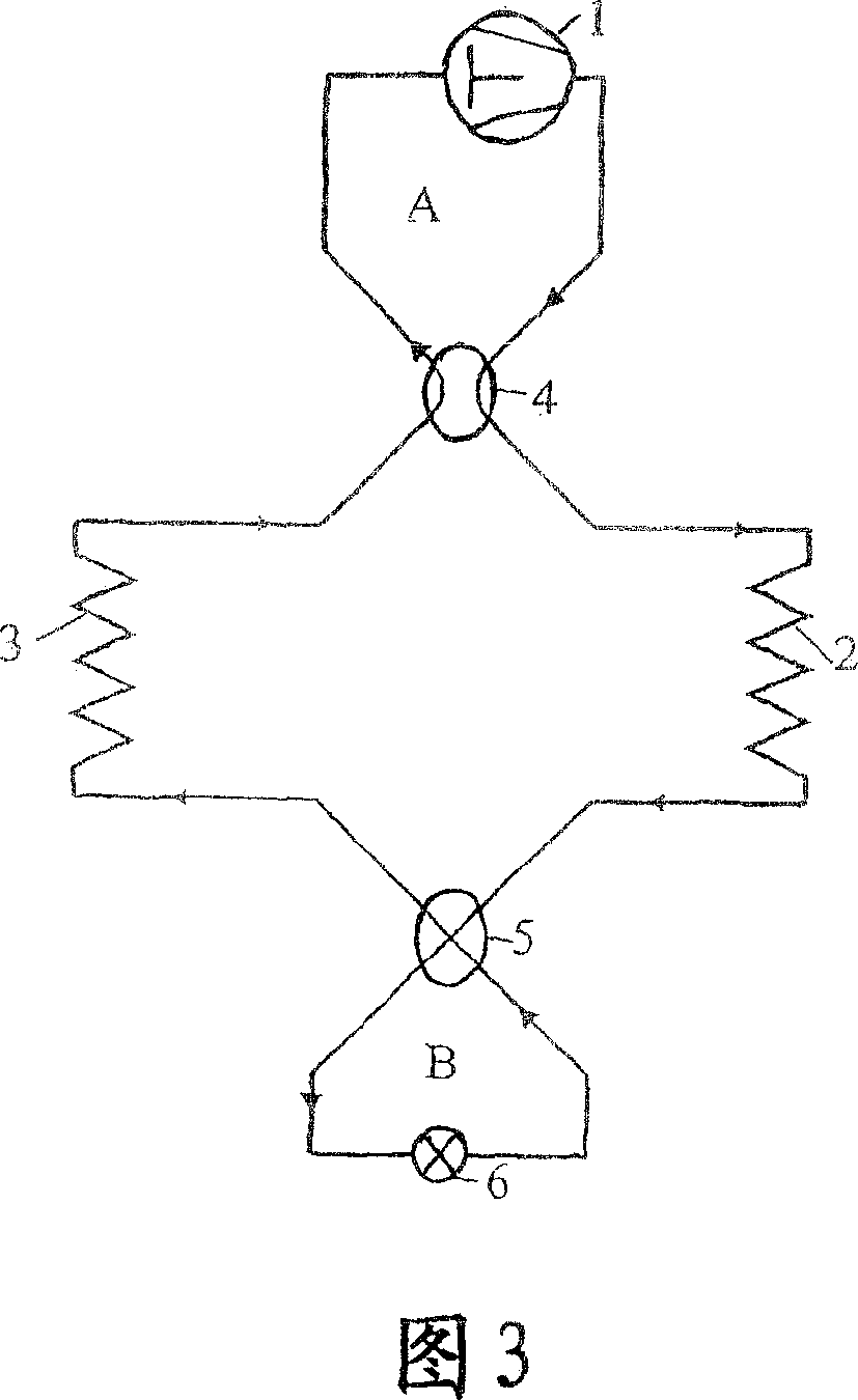
[0062] The first (basic) embodiment of the invention is for a single stage reversible vapor compression cycle, shown in FIG. 3 in heating mode operation and in FIG. 4 in cooling mode operation. According to the invention, the system comprises a compressor 1 , an internal heat exchanger 2 , an expansion device 6 (such as a throttle valve) and an external heat exchanger 3 , like known systems. It should be understood that the complete system has connecting lines in which a refrigerant circulates in order to form a closed main flow path. The first embodiment of the present invention is characterized in that two sub-routes are used, the first route A and the second route B are respectively connected to the main flow circuit through a first flow reversing device 4 and a second flow reversing device 5, and the reversing The device can be, for example, a four-way shutter. The compressor 1 and the expansion device 6 are arranged in the first sub-route A and in the second sub-route B ...

no. 2 example

[0070] Figures 5 and 6 respectively show schematic views of the second embodiment in heating and cooling mode operation. Compared to the first embodiment, it has a supplementary line circuit C comprising a heat desiccant exchanger 25 , an expansion device 23 and a valve 24 . The heat exchanger 25 has a dehumidifying function in the heating mode and works as a common evaporator in the cooling mode. In heating mode, some of the high pressure refrigerant is deflated through the expansion device 23 after reversing the device 5, where the refrigerant pressure is reduced to the evaporation pressure in the heat exchanger described above. The above-mentioned refrigerant is then evaporated by heat absorption in the heat exchanger 25 before it passes through the valve 24 . In this way, the interior air moves through this desiccant heat exchanger 25 before it is reheated by the interior heat exchanger 2, so as to provide dry air into the interior space for demisting purposes, such as in...

no. 3 example

[0072] Figures 7 and 8 show schematic views of a third embodiment operating in heating and cooling modes, respectively. Compared with the second embodiment, the pipeline circuit C relative to the main circuit is arranged in such a way that the internal heat exchangers 2 of the desiccant heat exchanger 25 are connected in series in the cooling mode, at this time by means of setting the flow changing devices 26 and 26 ' (eg inspection valve), which is contrary to the second embodiment, wherein the above-mentioned heat exchangers are connected in parallel, regardless of the working mode. The reversing of the system is the same as in the first embodiment, by changing the position of the two flow reversing devices 4 and 5, from heating mode to cooling mode and vice versa.


PUM


Abstract

Reversible vapor compression system including a compressor ( 1 ), an interior heat exchanger ( 2 ), an expansion device ( 6 ) and an exterior heat exchanger ( 3 ) connected by means of conduits in an operable relationship to form an integral main circuit. A first device is provided in the main circuit between the compressor and the interior heat exchanger, and a second device is provided on the opposite side of the main circuit between the interior and exterior heat exchangers to enable reversing of the system from cooling mode to heating mode and vice versa. The first and second device for reversing of the system include a first and second sub-circuit (A respectively B) each of which is connected with the main circuit through a flow reversing device ( 4 and 5 respectively). Included in the system solution is a reversible heat exchanger for refrigerant fluid, particularly carbon dioxide. It includes a number of interconnected sections arranged with air flow sequentially through the sections. The first and last sections are inter-connected whereby the refrigerant fluid flow in the heat exchanger can be changed from heating to cooling mode by means of flow changing devices provided between the respective sections.

Description

technical field [0001] The present invention relates to vapor compression systems, such as refrigeration, air conditioning, heat pump systems, and / or combinations thereof, operating under transcritical or subcritical conditions using any refrigerant and especially carbon dioxide, and more particularly, Relates to, but is not limited to, a device that operates as a reversible refrigeration / heat pump system. Background technique [0002] A non-reversible vapor compression system has in its basic form a main circuit with a compressor 1, a heat discharger 2, a heat absorber 3 and an expansion device 6, as shown in Figure 1 . The system described above can work in heating or cooling mode. In order to make this system reversible, that is, it can work as a heat pump and a refrigeration system at the same time, the existing technology uses different system designs, and changes or adds new components in the above-mentioned circuit to achieve this purpose. Such prior art techniques...

Claims


Application Information

Patent Timeline
Patent Type & Authority Patents(China)
IPC IPC(8): F25B13/00F25B9/00F25B1/10F25B40/00F25B47/02
CPCF24F3/1405F25B2309/061F25B13/00F25B2400/13F25B40/00F25B9/008F25B2313/023F25B2313/02732F25B2600/2501F25B2400/16F25B2313/02741F25B47/022F24F2003/1446F25B1/10
Inventor 科勒·阿弗莱特埃纳尔·布伦登阿明·哈夫纳彼得·奈克瑟约斯滕·彼得森哈瓦尔德·莱克斯泰德盖尔·斯凯于根格拉姆·R·扎克里
Owner SINVENT AS
Why Eureka
Try Eureka