Mold for producing centrifugal fan blade

A technology of centrifugal fan blades and molds, which is used in household appliances, other household appliances, applications, etc., can solve the problems of different strength, easy damage of blades, and long overall structure of centrifugal blades, so as to achieve the process of improving quality and demoulding handy effect

Pending Publication Date: 2022-02-11
宁波久欣世宇模具有限公司
View PDF8 Cites 0 Cited by
  • Summary
  • Abstract
  • Description
  • Claims
  • Application Information

AI Technical Summary

Problems solved by technology

[0004] The above-mentioned related technical solutions have the following defects: the overall structure of the above-mentioned centrifugal fan blade is long, and when the conventional injection mold is fed from one end to produce the centrifugal fan blade, it may cause the blades at both ends of the fan blade main board to be formed and condensed. The time is different and the strength is different. When using the centrifugal fan blade, it may cause the fan blade on one side to be more easily damaged

Method used


Image

  • Mold for producing centrifugal fan blade
  • Mold for producing centrifugal fan blade
  • Mold for producing centrifugal fan blade

Examples


Embodiment Construction

[0039] The following is attached Figure 1-7 The application is described in further detail.

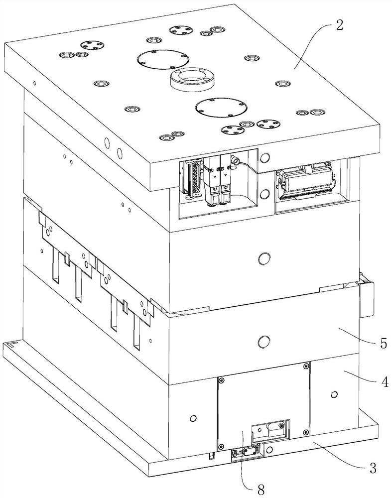
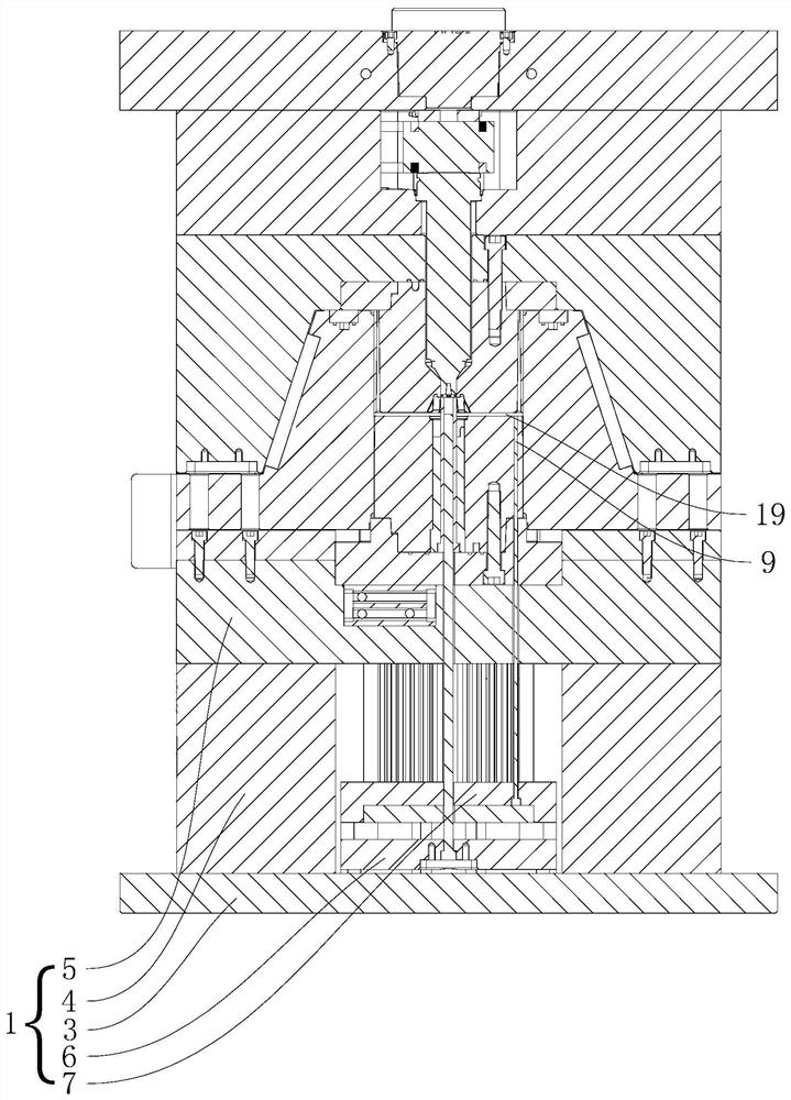
[0040] see figure 1 and figure 2 ,, a mold for producing centrifugal fan blades, including a movable mold 1 fixed in the injection molding machine that moves with the internal mechanism of the injection molding machine and a fixed mold 2 fixed in the injection molding machine, the movable mold 1 and the fixed mold 2 are interlocked combine.

[0041] The movable mold 1 includes a lower template 3 that can be fixed inside the injection molding machine by bolts, two square irons 4 that are fixed on one end of the lower template 3 by bolts at parallel intervals, and fixed on the bottom of the square iron 4 away from the end of the lower template 3 by bolts. Template 5, thimble plate 6 installed between two square irons 4, face needle plate 7 located at the end of thimble plate 6 close to lower formwork 5, two pieces of square iron 4 form ejector plate 6 and face needle plate 7. A c...


PUM


Abstract

The invention relates to a mold for producing a centrifugal fan blade. The mold comprises a movable mold which is fixed in an injection molding machine and moves along with an internal mechanism of the injection molding machine and a fixed mold which is fixed in the injection molding machine; the movable mold and the fixed mold are buckled to each other; a first mold core is arranged at one end, close to the fixed mold, of the movable mold; a second mold core aligned to the first mold core is arranged at the end, close to the movable mold, of the fixed mold; fan blade forming grooves for forming fan blades are evenly formed in the circumferential side ends of the first mold core and the second mold core in the circumferential direction; and forming sliding blocks wrapping the first mold core and the second mold core are slidably arranged on the portions, on the two sides of the first mold core, of the movable mold; a forming cavity is formed among the two forming sliding blocks, the first mold core and the second mold core; a main plate forming groove for forming a fan blade main plate is formed between the first mold core and the second mold core; the main plate forming groove is communicated with the fan blade forming grooves; and a feeding channel communicated with the main plate forming groove is formed in the middle of the second mold core. With the mold adopted, the quality of the centrifugal fan blade can be improved.

Description

technical field [0001] The present application relates to the technical field of injection molds, in particular to a mold for producing centrifugal fan blades. Background technique [0002] At present, injection mold is a tool for producing plastic products; it is also a tool for giving plastic products a complete structure and precise dimensions. Injection molding is a processing method used in the mass production of certain complex-shaped parts. Specifically, it refers to injecting the heated and melted plastic into the mold cavity under high pressure from the injection molding machine, and after cooling and solidifying, a molded product is obtained. [0003] Existing a centrifugal blade, such as Figure 7 As shown, it includes the main board of the fan blade in the shape of a disk in the middle, the fan blades integrally formed on both ends of the main board of the fan blade, and the stability ring integrally formed on the end of the blade away from the main board of the...

Claims


Application Information

Patent Timeline
Patent Type & Authority Applications(China)
IPC IPC(8): B29C45/26B29C45/33B29C45/40B29C45/64B29L31/08
CPCB29C45/2602B29C45/33B29C45/401B29C45/64B29L2031/082
Inventor 李世村
Owner 宁波久欣世宇模具有限公司
Why Eureka
Try Eureka