
Protective glass defect detection equipment

A defect detection and glass protection technology, applied in mechanical equipment, measuring devices, instruments, etc., can solve the problems of easy deviation, limit, and scratches on the glass surface of the detection camera position.

Active Publication Date: 2022-03-18
江苏晟尔检测仪器有限公司
View PDF5 Cites 0 Cited by
  • Summary
  • Abstract
  • Description
  • Claims
  • Application Information

AI Technical Summary

Problems solved by technology

For example, there may be defects such as scratches, chipping, dirt, and poor silk screen printing on the glass surface.
These surface appearance defects directly affect the appearance of smart devices, etc.
[0003] The existing protective glass defect detection equipment realizes the construction of an active optical detection hardware system for the appearance of intelligent equipment protective glass based on a linear array industrial camera, which greatly improves the detection efficiency of industrial appearance detection. However, after the detection camera is installed, the actual adjustment is inconvenient. , and it is not convenient to limit the position of the detection camera after adjustment. In the process of actual use, the position of the detection camera is prone to shift, which will affect the detection of the detection camera.

Method used


Image

  • Protective glass defect detection equipment
  • Protective glass defect detection equipment
  • Protective glass defect detection equipment

Examples


Embodiment 1

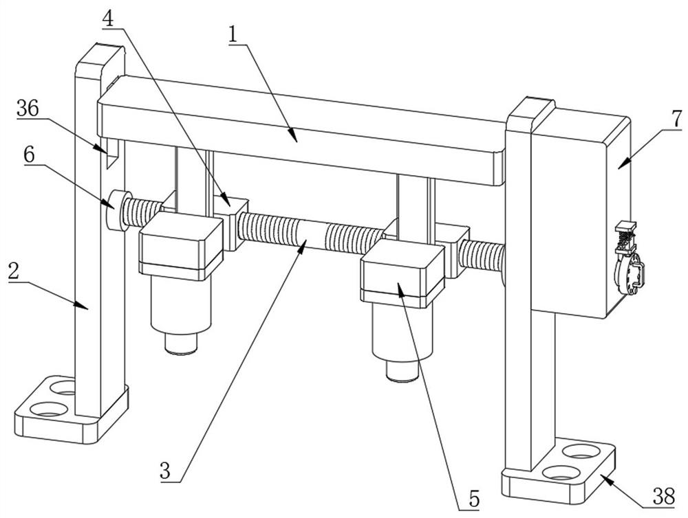
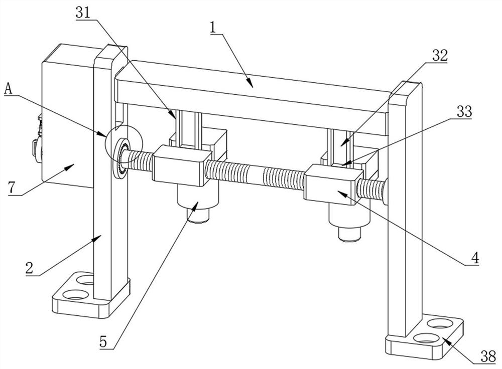
[0033] Embodiment one, by Figure 1 to Figure 8 Given, the present invention includes a support top plate 1, both sides of the support top plate 1 are provided with support side plates 2, a two-way screw rod 3 is provided below the support top plate 1, and two movable blocks are arranged between the two support side plates 2 4. The two-way screw rod 3 runs through two movable blocks 4, and the connection between the movable block 4 and the two-way screw rod 3 is threaded connection. There are two detection camera bodies 5 under the supporting top plate 1, and the detection camera body 5 and the movable block 4 is provided with a limit slide unit matched with the supporting top plate 1, one end of the two-way screw rod 3 is connected with one side of one of the supporting side plates 2 through the first bearing 6, and the other end of the two-way screw rod 3 runs through the other The side plate 2 is supported, and the second bearing 11 is provided at the penetration of the two...

Embodiment 2

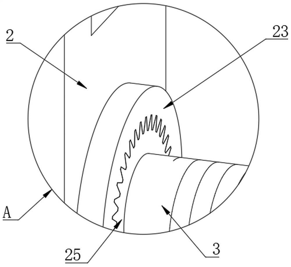
[0035] Embodiment two, on the basis of embodiment one, by figure 1 , figure 2 , image 3 , Figure 4 , Figure 6 with Figure 7 Given, the limiting rotation assembly includes a groove 16 provided at one end of the two-way screw rod 3, and one side of the inner wall of the groove 16 is provided with a card groove 17, and one end of the rotating shaft 13 is fixedly connected with a guide post 18, and one end of the guide post 18 Located in the groove 16, the end of the guide column 18 away from the rotating shaft 13 is fixedly connected with a block 19, and one side of the supporting side plate 2 is provided with a first gear 25, and the two-way screw rod 3 runs through the first gear 25, and the two-way wire The rod 3 is fixedly connected with the first gear 25, and the outside of the first gear 25 is provided with a gear ring 23. The gear ring 23 and the rotating shaft 13 are connected through a rotating part. The rotating part includes a fixed ring 21 sleeved on the outs...

Embodiment 3

[0037] Embodiment three, on the basis of embodiment one, by figure 1 , Figure 4 , Figure 5 with Figure 8 Provided, the movable engagement limit assembly includes a movable plate 26 arranged in the control box 7, the rotating shaft 13 runs through the movable plate 26, the fifth bearing 29 is provided at the penetration of the rotating shaft 13 and the movable plate 26, and the inner wall of one side of the control box 7 Fixedly connected with a positioning plate 30, and the positioning plate 30 runs through the movable plate 26, one side of the movable plate 26 is fixedly connected with a tooth plate 28, the control box 7 is provided with a second gear 27, and the threaded column 10 runs through the second gear 27, And the threaded column 10 is fixedly connected with the second gear 27, the limit sliding unit includes a connecting plate 31 arranged between the movable block 4 and the detection camera body 5, one side of the connection plate 31 is fixedly connected with on...


PUM


Abstract

The invention relates to the technical field of computer vision detection, and discloses protective glass defect detection equipment, which solves the problem that after the detection camera is installed, the actual adjustment is relatively inconvenient, and it is not convenient to limit the position of the detection camera after adjustment. During the process, the position of the detection camera is prone to shift, which in turn affects the detection of the detection camera. It includes a support top plate. Both sides of the support top plate are provided with support side plates. There are two movable blocks between the two supporting side plates, the two-way screw rod runs through the two movable blocks, and the connection mode between the movable block and the two-way screw rod is screw connection, and two detection camera bodies are arranged under the supporting top plate; The position of the detection camera body is adjusted. After the position of the detection camera body is adjusted, the position of the detection camera body can be limited to avoid the position deviation of the detection camera body during use.

Description

technical field [0001] The invention belongs to the technical field of computer vision detection, in particular to protective glass defect detection equipment. Background technique [0002] With the development of science and technology and the improvement of living standards, smart devices have gradually become one of the necessities of people's life. Smart device protective glass is mainly used for external protection, aesthetics or decoration of smart devices. For example, the touch screen protective glass of a mobile phone or tablet computer and the rear glass on the back are used to protect the core components such as chip circuits inside the device, and at the same time play a role in beautification. There are great differences in the production process of protective glass for smart devices made of different materials, but without exception, they all have higher and higher requirements for their appearance. For example, there may be defects such as scratches, chippin...

Claims


Application Information

Patent Timeline
Patent Type & Authority Patents(China)
IPC IPC(8): G01N21/958G01N21/01F16M11/04F16M11/18
CPCG01N21/958G01N21/01F16M11/043F16M11/18
Inventor 孙珍同张忠贵
Owner 江苏晟尔检测仪器有限公司
Learn More