
Protective device capable of preventing optical fiber connector from being damaged

A fiber optic connector and protective device technology, which is applied in the coupling of optical waveguide, light guide, optics, etc., can solve the problems of easy detachment of optical fiber cable and optical fiber connector, poor protective cover effect, and influence on normal use. The time of manual operation is good, the protection effect is good, and the effect of not easy to accumulate dust

Active Publication Date: 2022-02-11
YINGTAN MINGKANG COMM TECH CO LTD
View PDF6 Cites 0 Cited by
  • Summary
  • Abstract
  • Description
  • Claims
  • Application Information

AI Technical Summary

Problems solved by technology

[0004]In order to overcome the fact that most of the optical fiber connectors on the market do not have effective protection functions, which affect the service life, and the simple use of protective sleeves for protection is not effective and troublesome to disassemble, and at the same time The optical fiber cable and the optical fiber connector are easy to detach, which affects the normal use of the shortcomings, technical problems: provide a protective device that can prevent the optical fiber cable from detachment, has a good protective effect, and is easy to disassemble to prevent damage to the optical fiber connector

Method used


Image

  • Protective device capable of preventing optical fiber connector from being damaged
  • Protective device capable of preventing optical fiber connector from being damaged
  • Protective device capable of preventing optical fiber connector from being damaged

Examples


Embodiment 1

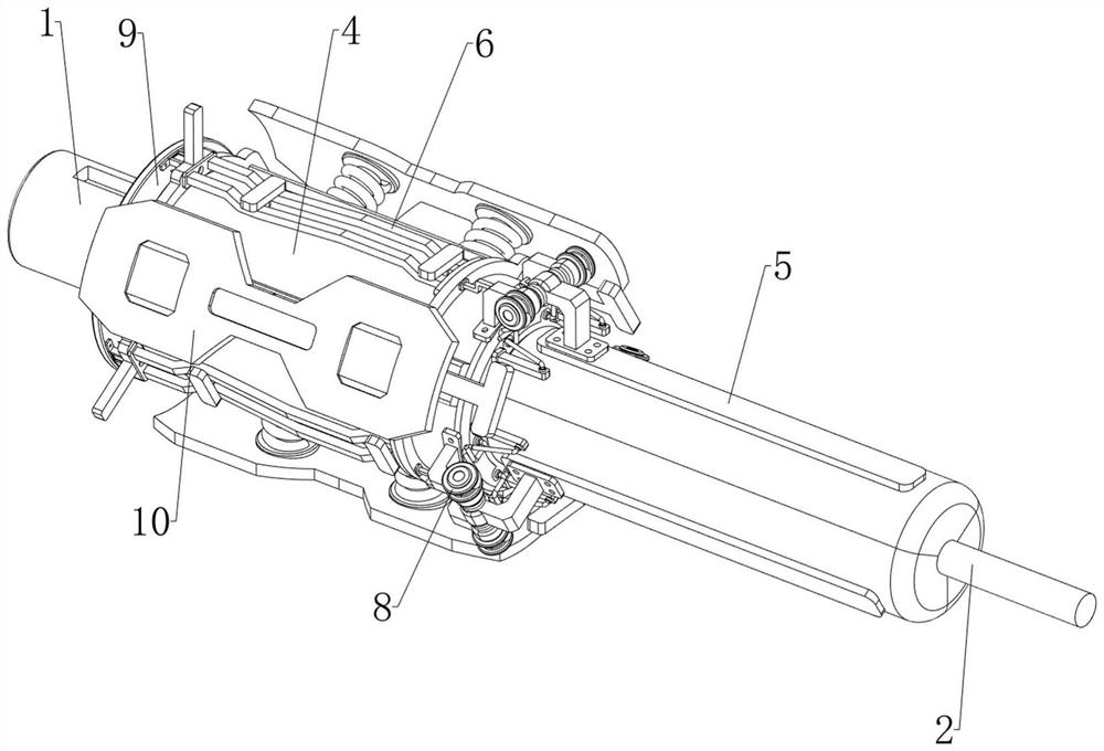
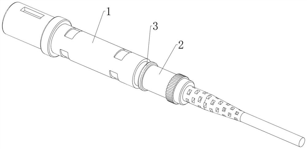
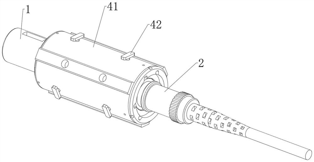
[0041] A guard that prevents damage to fiber optic connectors such as Figure 1-6 As shown, it includes an optical fiber connector 1, an optical fiber cable 2, a push ring 3, a protection mechanism 4 and a protection mechanism 5. An optical fiber cable 2 for transmitting optical signals is installed on the right side of the optical fiber connector 1, and an optical fiber cable 2 is installed on the left side of the optical fiber cable 2. The push ring 3 is covered with a protection mechanism 4 on the optical fiber connector 1. The protection mechanism 4 can prevent the optical fiber connector 1 from being damaged. A protection mechanism 5 for protecting the optical fiber 2 is provided on the right side of the protection mechanism 4.

[0042] The protection mechanism 4 includes a protective sleeve 41, a first connecting rod 42, a positioning block 43 and a first connecting spring 44. The optical fiber connector 1 is covered with a protective sleeve 41. The protective sleeve 41 c...

Embodiment 2

[0046] On the basis of Example 1, such as figure 1 , Figure 7 , Figure 8 , Figure 9 , Figure 10 , Figure 11 , Figure 12 , Figure 13 , Figure 14 , Figure 15 , Figure 16 , Figure 17 and Figure 18 As shown, it also includes a disengagement mechanism 6 that can save manpower. The disengagement mechanism 6 includes a first connecting ring 61, a first connecting block 62, a second connecting ring 63, a snap bead 64 and a second connecting spring 65, and the protective sleeve 41 The right sliding type is provided with a first connecting ring 61, and the left sliding type of the protective cover 41 is provided with a second connecting ring 63, and three first connecting rings 61 and 63 are uniformly connected in a circumferential direction between the first connecting ring 61 and the second connecting ring 63. Connecting block 62, every first connecting block 62 is all slidably connected with two first connecting rods 42 on the same side, and the left and right ...


PUM


Abstract

The invention relates to a protection device, in particular to a protection device capable of preventing an optical fiber connector from being damaged. The protection device capable of preventing the optical fiber connector from being damaged is capable of preventing the optical fiber from being separated, good in protection effect, convenient to disassemble and capable of preventing the optical fiber connector from being damaged. The protection device comprises the optical fiber connector, an optical fiber cable, a push ring, a protection mechanism and a defending mechanism, the right side of the optical fiber connector is provided with the optical fiber cable which can transmit optical signals, the left side of the optical fiber cable is provided with the push ring, the optical fiber connector is sleeved with the protection mechanism used for protection, and the right side of the protection mechanism is provided with the defending mechanism, and the defending mechanism can prevent the optical fiber from being damaged. The optical fiber connector can be clamped through a positioning block, so that the protective sleeve can protect the optical fiber connector, the outer wall of the optical fiber connector is prevented from being damaged, and the protection effect is better.

Description

technical field [0001] The invention relates to a protection device, in particular to a protection device capable of preventing damage to an optical fiber connector. Background technique [0002] The main function of the optical fiber connector is to quickly connect two optical fibers so that the optical signal can be continuous to form an optical path. It is used for re-pluggable connection devices between optical fibers. The pollution and damage of the optical interface cause the loss of the optical link to increase, resulting in the failure of the optical link, and if the optical fiber is exposed to the environment for a long time, the optical port will be polluted by dust, resulting in damage to the optical fiber connector, and the optical fiber cable is connected with the When the fiber optic connectors are connected, if the fiber optic cable is pulled, it is easy to detach from the fiber optic connector, affecting normal use. Most fiber optic connectors on the market d...

Claims


Application Information

Patent Timeline
Patent Type & Authority Applications(China)
IPC IPC(8): G02B6/38G02B6/44
CPCG02B6/38G02B6/4429G02B6/443
Inventor 何奎德祝福舒富镐
Owner YINGTAN MINGKANG COMM TECH CO LTD
Learn More