
Multi-energy complementary stable energy supply system

An energy storage system and energy supply technology, applied in the field of multi-energy complementary and stable energy supply systems, can solve problems such as strong output fluctuations, increased pressure on power grid peak regulation and frequency regulation, and new energy energy utilization efficiency needs to be improved to achieve economic benefits The effect of high and stable supply

Pending Publication Date: 2022-02-11
HUANENG CLEAN ENERGY RES INST
View PDF0 Cites 0 Cited by
  • Summary
  • Abstract
  • Description
  • Claims
  • Application Information

AI Technical Summary

Problems solved by technology

At present, the main problem of wind energy, solar energy, etc. is that the energy source is strongly dependent on weather conditions, and the output of wind power and photovoltaic power generation is highly volatile and discontinuous. After being integrated into the grid, the pressure of peak regulation and frequency regulation of the grid will be increased, which seriously limits the large-scale use of new energy. develop
Energy storage technology is a key means to achieve coordinated energy management and optimal matching. At present, this technology has not yet fully played a role in the new energy system, resulting in low energy utilization efficiency of the new energy system.
[0003] The current development of new energy has the following problems: wind energy and solar energy depend on weather conditions, and their power generation output is highly volatile and discontinuous, which is not conducive to grid connection; the current new energy system mainly uses a single energy storage form to store energy, which has not been fully utilized The peak-shaving and frequency-regulating functions of various energy storage technologies, the energy utilization efficiency of new energy needs to be improved

Method used


Image

  • Multi-energy complementary stable energy supply system
  • Multi-energy complementary stable energy supply system
  • Multi-energy complementary stable energy supply system

Examples


Embodiment Construction

[0041] In order to make the purpose, technical solutions and advantages of the embodiments of the present invention clearer, the technical solutions in the embodiments of the present invention will be clearly and completely described below in conjunction with the drawings in the embodiments of the present invention. Obviously, the described embodiments It is a part of embodiments of the present invention, but not all embodiments. Based on the embodiments of the present invention, all other embodiments obtained by persons of ordinary skill in the art without making creative efforts belong to the protection scope of the present invention.

[0042] In this application, the term "comprises", "comprises" or any other variation thereof is intended to cover a non-exclusive inclusion such that a process, method, article, or apparatus comprising a set of elements includes not only those elements, but also includes none. other elements specifically listed, or also include elements inher...


PUM


Abstract

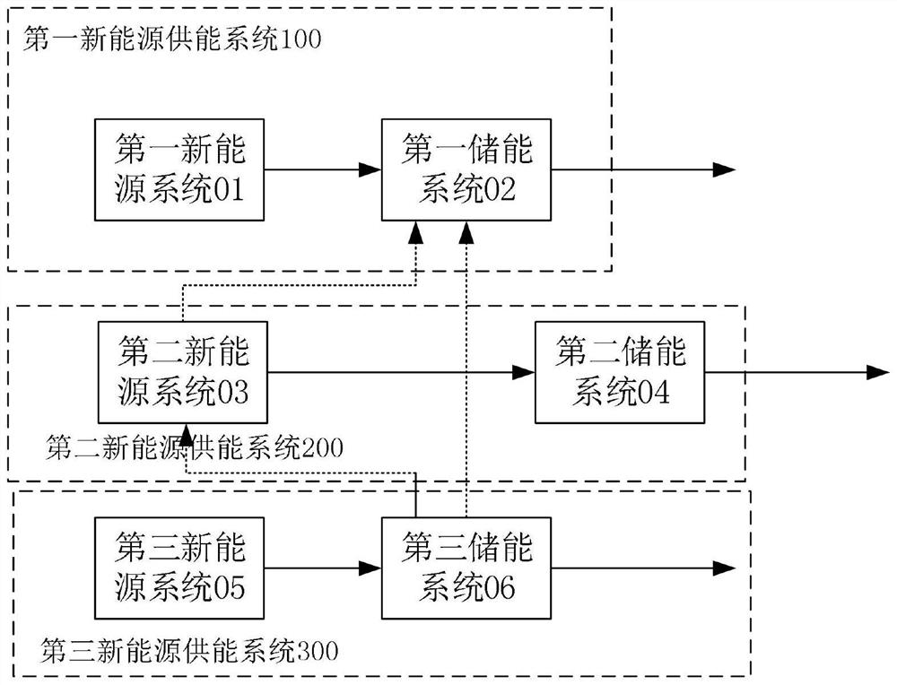
The invention provides a multi-energy complementary stable energy supply system. The multi-energy complementary stable energy supply system comprises a plurality of new energy energy supply systems; the output end of a first new energy system in the first new energy supply system is connected with the input end of a first energy storage system; the output end of a second new energy system in the second new energy supply system is connected with the input end of a second energy storage system; the output end of a third new energy system in the third new energy supply system is connected with the input end of a third energy storage system; the first new energy system, the second new energy system and the third new energy system are different; the first energy storage system, the second energy storage system and the third energy storage system are different; the storage forms of the first energy storage system, the second energy storage system and the third energy storage system can be mutually converted; and therefore, the cooperative management effect of various energy storage technologies is achieved in the multi-energy complementary stable energy supply system, stable supply of heat energy and electric energy is achieved, and economic benefits are high.

Description

technical field [0001] The invention belongs to the technical field of new energy energy supply systems, and more specifically relates to a multi-energy complementary and stable energy supply system. Background technique [0002] Vigorously developing new energy is an inevitable choice to achieve the goal of "dual carbon", and it is of great significance for coping with climate change and promoting sustainable development. At present, the main problem of wind energy, solar energy, etc. is that the energy source is strongly dependent on weather conditions, and the output of wind power and photovoltaic power generation is highly volatile and discontinuous. After being integrated into the power grid, the pressure of peak regulation and frequency regulation of the power grid is increased, which seriously limits the large-scale use of new energy. develop. Energy storage technology is a key means to achieve coordinated energy management and optimal matching. At present, this tech...

Claims


Application Information

Patent Timeline
IPC IPC(8): H02J3/38H02J3/28H02J3/32H02J3/24H02J3/06H02J15/00
CPCH02J3/38H02J3/28H02J3/32H02J3/241H02J3/06H02J15/006H02J15/00H02J2300/24H02J2300/28Y02E10/56Y02E60/36Y02E70/30
Inventor 王会钟迪黄永琪彭烁周贤安航蔡浩飞
Owner HUANENG CLEAN ENERGY RES INST
Learn More