Adjustable calibration type electroslag pressure welding tool

An electroslag pressure welding and adjustable technology, which is applied in the field of measuring equipment and electroslag pressure welding, can solve the problems of large inclination angle, simple structure of measuring instruments, and inability to meet the needs of workers for measuring and using, so as to reduce deviation and ensure The effect on overall security

Pending Publication Date: 2022-02-15
HENAN UNIVERSITY
View PDF9 Cites 0 Cited by
  • Summary
  • Abstract
  • Description
  • Claims
  • Application Information

AI Technical Summary

Problems solved by technology

[0007] During the welding construction process of the existing project, it was found that due to the error in the welding process during joint welding, the inclination angle between the upper and lower welded steel bars may be too large; the offset axis distance of the upper steel bar exceeds the diameter of the steel bar; the welding envelope is convex The height does not meet the standard, and the existing measuring instrument has a simple structure and cannot meet the needs of workers for measurement and use. The present invention provides an adjustable and calibrated electroslag pressure welding tool

Method used


Image

  • Adjustable calibration type electroslag pressure welding tool
  • Adjustable calibration type electroslag pressure welding tool
  • Adjustable calibration type electroslag pressure welding tool

Examples


Embodiment 1

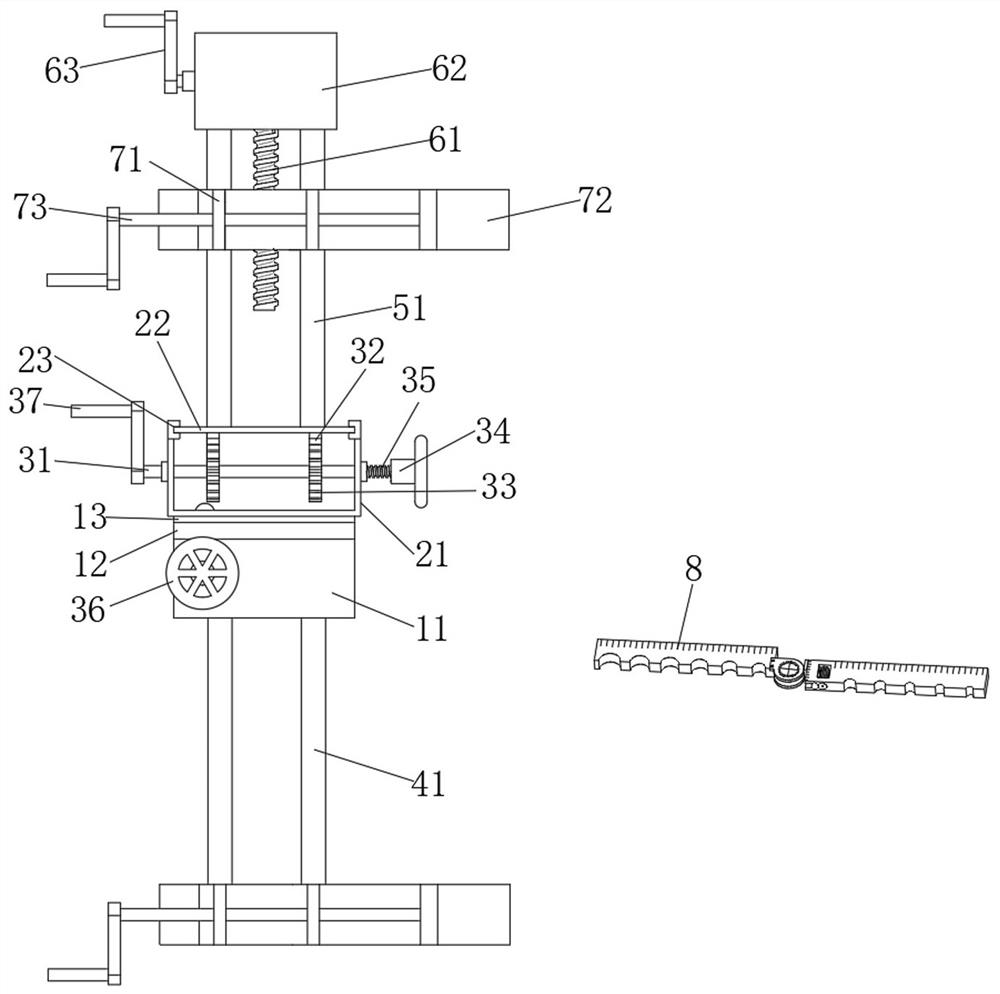
[0038] according to Figure 1-5 As shown, it includes a docking fixture and a measuring instrument 8 arranged on one side of the docking fixture. The docking fixture includes an offset mechanism, an upper clamping mechanism, and a lower clamping mechanism;

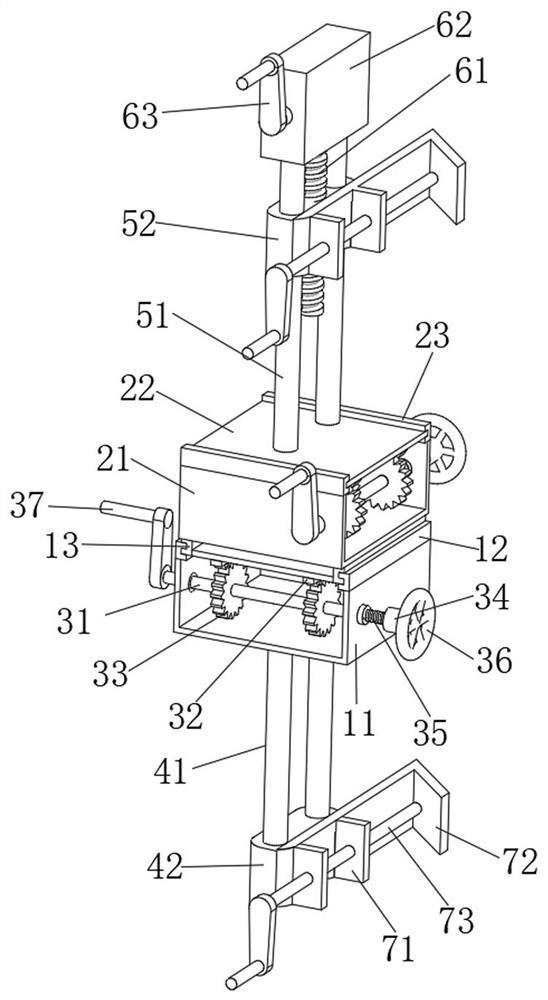
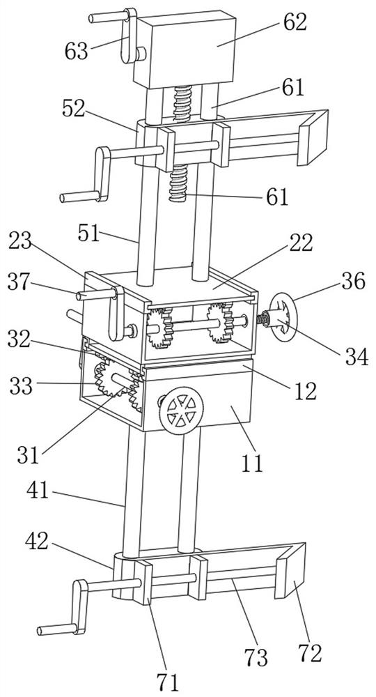
[0039] Such as figure 1 , figure 2and image 3 As shown, the offset mechanism includes an X-axis support 11, a lower seat 13, a lower adjustment assembly, a Y-axis support 21, an upper slide plate 22, and an upper adjustment assembly; the X-axis support 11 is connected to the top of the lower clamping mechanism, and X Both side wall tops of the shaft support 11 are equipped with sliding rails 12. The sliding seat 13 includes two U-shaped plates and a horizontal plate. The two U-shaped plates are respectively slidably connected with the two sliding rails 12. Between the U-shaped plates, the lower adjustment assembly is installed on the X-axis support 11 and can make the slide seat 13 slide axially along the slide rail 1...

Embodiment 2

[0050] On the basis of Embodiment 1, the similarities between this embodiment and Embodiment 1 will not be repeated, and the differences are as follows: Another method of using the measuring instrument 8, when the upper and lower steel bars are connected and welded to produce a certain offset , by clamping the lower steel bar through the measuring hole 89 on the lower specification ruler 82, when the axes of the upper and lower steel bars are not on the same axis, move the lower specification ruler 82 close to the upper steel bar for measurement, and in the process, the worm screw 88 can be slowly rotated, and the worm screw 88 Engage the transmission worm gear 812, and then under the joint action of the slider 811, the connecting block 810 and the limit hole 87, the connecting shaft 86, the connecting ring 83 and the upper specification ruler 81 are moved to the upper side of the steel bar, and the upper specification ruler 81 When the measuring hole 89 is close to the upper s...

Embodiment 3

[0052] On the basis of Embodiment 1, the similarities between this embodiment and Embodiment 1 will not be repeated, and the differences are as follows: Another method of using the measuring instrument 8, when the axes of the upper and lower steel bars are not on the same axis, by welding The package is placed at the connecting ring 83, and the upper specification ruler 81 and the lower specification ruler 82 are slightly rotated so that the upper specification ruler 81 and the lower specification ruler 82 are close to the upper and lower steel bars, and the upper specification ruler 81 and the lower specification ruler 82 are close to the steel bars. During the process, the movement of the connecting shaft 86 and the connecting ring 83 produces a certain angle offset, and then through the cooperation of the cross pointer 91 and the dial 92, the bending angle of the upper and lower steel bars can be obtained by measuring the position of the pointer rotation.


PUM


Abstract

The invention discloses an adjustable calibration type electroslag pressure welding tool, and relates to the field of electroslag pressure welding butt joint and measuring appliances. The adjustable calibration type electroslag pressure welding tool comprises a butt joint clamp and a measuring instrument arranged at one side of the butt joint clamp, the butt joint clamp comprises a deviation mechanism, an upper clamping mechanism and a lower clamping mechanism, and the deviation mechanism comprises an X-axis support, a lower sliding seat, a lower adjusting assembly, a Y-axis support, an upper sliding plate and an upper adjusting assembly. The X-axis support is connected with the top end of the lower clamping mechanism, lower sliding rails are mounted at the tops of the two side walls of the X-axis support, and a lower sliding seat is arranged between the two lower sliding rails. By arranging the lower adjusting assembly and the upper adjusting assembly, the angle and offset of an upper reinforcing steel bar can be adjusted, it is guaranteed that the axes of the upper reinforcing steel bar and the lower reinforcing steel bar are located at the same position after the reinforcing steel bar is welded, and the deviation angle of the welded steel bars meets the welding specification requirement; by adjusting and calibrating the butt joint of the upper steel bars and the lower steel bars, deviation generated in the welding process is reduced, and the overall safety of the structure is guaranteed.

Description

technical field [0001] The invention belongs to the field of electroslag pressure welding butt joint and measuring equipment, and in particular relates to an adjustable and calibrated electroslag pressure welding equipment. Background technique [0002] The electroslag pressure welding of steel bars is to place two steel bars in a vertical or oblique (within the range of inclination) docking form, and use the current to pass through the gap between the two steel bars to form an arc process and an electroslag process under the desiccant layer. Arc heat and resistance heat, a welding method that melts steel bars and pressurizes. Vertical reinforcement electroslag pressure welding is a kind of reinforcement welding technology pioneered in my country. It has the characteristics of convenient construction, low cost and simple operation, which makes it widely used in the field of vertical reinforcement of buildings and other structural parts in my country. [0003] However, in th...

Claims


Application Information

Patent Timeline
Patent Type & Authority Applications(China)
IPC IPC(8): B23K25/00
CPCB23K25/00
Inventor 马少春肖慧敏姚于迪鲍鹏
Owner HENAN UNIVERSITY
Why Eureka
Try Eureka