Engineering material vehicle and slip form paver

A material vehicle and engineering technology, applied in the direction of roads, road repairs, roads, etc., can solve the problems of increased vehicle cost, vehicle size, low construction efficiency, and poor quality, so as to improve work efficiency and construction quality, and evenly pave operations , The effect of low manufacturing cost

Pending Publication Date: 2022-02-15
中汽旺磐(珠海)机床有限公司
View PDF6 Cites 1 Cited by
  • Summary
  • Abstract
  • Description
  • Claims
  • Application Information

AI Technical Summary

Problems solved by technology

The size of the current engineering vehicle is too large to be suitable for pavement paving on small construction sites (such as permeable concrete paving of light-weight roads such as sidewalks, grounds in communities, and sports tracks)
The discharge opening of the concrete tank truck is relatively low. After the material is discharged onto the engineering vehicle, due to the low height difference between the ground and the viscous material such as concrete, the engineering vehicle cannot uniformly and quickly discharge the material for paving. Material transportation and The problem that the paving operation of engineering vehicles cannot be well coordinated, resulting in low construction efficiency and poor quality
Although it is theoretically possible to configure the conveyor belt to drive the material on the engineering vehicle, this will undoubtedly increase the cost of the vehicle and the size of the vehicle, etc., which is not suitable for small site construction

Method used


Image

  • Engineering material vehicle and slip form paver
  • Engineering material vehicle and slip form paver
  • Engineering material vehicle and slip form paver

Examples


Embodiment 1

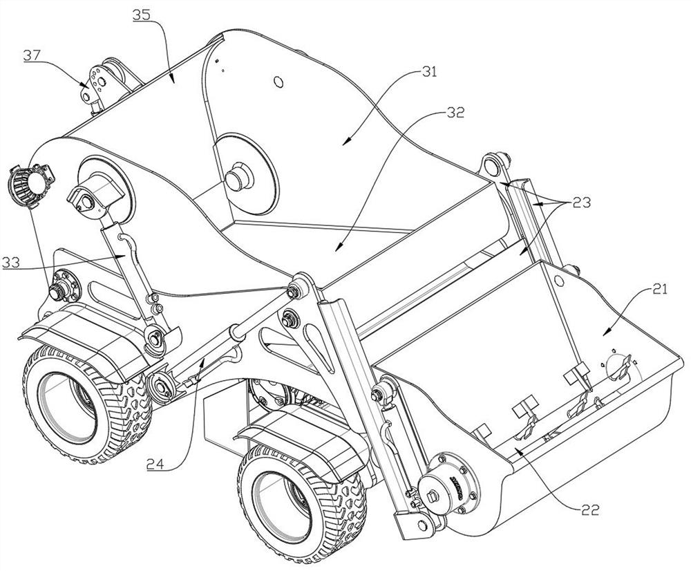
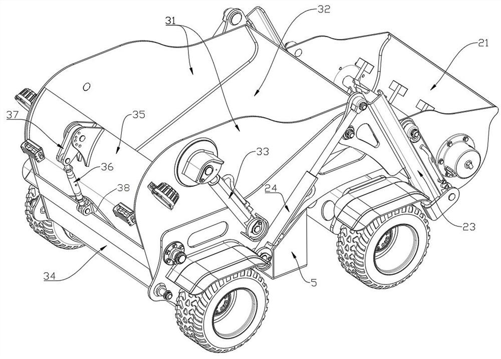
[0033] The engineering material truck of this embodiment includes a vehicle frame 1 , a discharge hopper mechanism 2 , a conveying hopper 3 and a power assembly 5 .

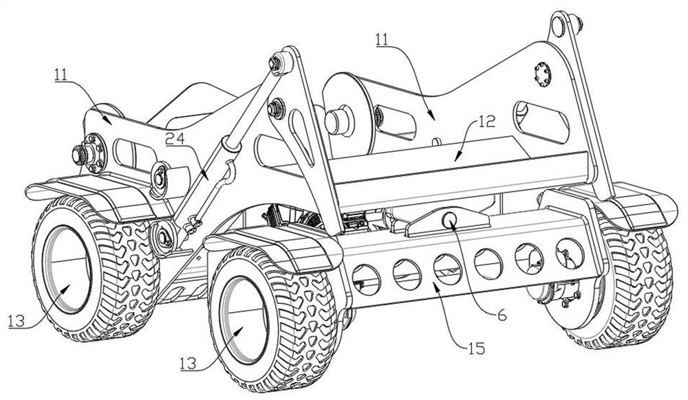
[0034] The vehicle frame 1 is a plate beam structure, which is convenient for integrated installation of accessories such as the discharge hopper mechanism 2, the conveying hopper 3, and the sliding mold attachment 4. Such as image 3 and Figure 4 As shown, the vehicle frame 1 includes side panels 11 and bottom panels I12 arranged left and right. The bottom of the vehicle frame 1 is arranged with a front bridge 15 and a rear bridge 14 front and back, one of the front bridge 15 or the rear bridge 14 is hinged with the vehicle frame 1, and the other is fixedly connected with the vehicle frame 1; Wheels 13 are mounted on both sides of the front bridge 15 and the rear bridge 14 respectively. Such as image 3 As shown, in this embodiment, the front bridge frame 15 is hinged on the bottom plate 12I through the pin...

Embodiment 2

[0041] The engineering material truck of this embodiment includes a vehicle frame 1, a discharge hopper mechanism 2, a delivery hopper 3 and a power assembly 5, and its structural arrangement is similar to that of the engineering material truck of Embodiment 1. The structure is different.

[0042] The unloading hopper 21 of the unloading hopper mechanism 2 of the present embodiment is fixedly connected on the unloading frame 23, and can also be set as an adjustable height installation position (such as setting an array of mounting holes with different heights on the unloading frame 23). In the present embodiment, no chute is provided on the unloading rack 23 and no pulleys are provided on the unloading hopper 21, and the unloading rack 23 is retained to turn over the unloading structure of the oil cylinder I 24 to reduce manufacturing costs.

[0043]The slip form paver 4 configured in the slip form paver of this embodiment is different from that of the slip form paver of the f...


PUM


Abstract

The invention belongs to the vehicle technology for building construction, and particularly relates to an engineering material vehicle, which comprises a vehicle frame, a conveying hopper is arranged on a frame body of the vehicle frame, and a discharging port is formed in the rear end of the conveying hopper. The material vehicle can continuously load, unload and convey construction materials in real time, is simple in structure, is particularly suitable for paving various concrete pavements in small sites, and is high in whole vehicle integration degree and low in cost. A slip form accessory is assembled at the rear end of the engineering material vehicle, so that the functions of loading, unloading, conveying and paving can be realized.

Description

technical field [0001] The invention belongs to the vehicle technology for building construction, in particular to an engineering material vehicle and a slip form paver. Background technique [0002] In the construction of various concrete pavements, the commonly used engineering vehicles are generally equipped with slip form attachments, and the concrete materials are transported to the construction site by transport tank trucks. The current engineering vehicles are large in size and cannot be applied to paving pavements with small construction sites (such as permeable concrete paving for lightweight roads such as sidewalks, grounds in communities, and sports tracks). The discharge opening of the concrete tank truck is relatively low. After the material is discharged onto the engineering vehicle, due to the low height difference between the ground and the viscous material such as concrete, the engineering vehicle cannot uniformly and quickly discharge the material for pavin...

Claims


Application Information

Patent Timeline
Patent Type & Authority Applications(China)
IPC IPC(8): E01C19/18
CPCE01C19/18E01C19/185
Inventor 杨海麟
Owner 中汽旺磐(珠海)机床有限公司
Why Eureka
Try Eureka