

Piston shoe and supporting disc friction structure
A technology for supporting discs and sliding shoes, which is applied to parts of pumping devices for elastic fluids, liquid displacement machines, variable displacement pump components, etc., and can solve the problem of easy wear of sliding shoes and poor stability of frictional movement of sliding shoes , uneven friction between the sliding shoe and the support plate, etc., to reduce the working load, improve the service life and work reliability
- Summary
- Abstract
- Description
- Claims
- Application Information
AI Technical Summary
Problems solved by technology
Method used
Image

Examples
Embodiment 1
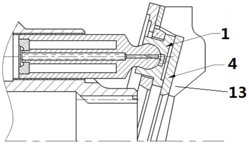
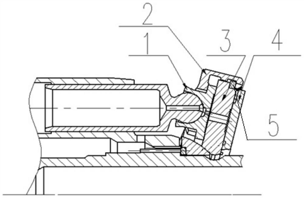
[0025] Embodiment 1 provides a friction structure between a sliding shoe and a supporting disc, including a sliding shoe 1, a friction conversion disc 3, a supporting disc 4 and a cage 2; the cage is used to hold the sliding shoe;
[0026] The friction transformation disc is arranged between the sliding shoe and the support disc;
[0027] forming a connection from the outer edge of the cage to the outer edge of the friction conversion disk, so that the cage and the friction conversion disk can rotate integrally;
[0028] The disk surface of the friction transformation disk corresponding to the support disk is the friction surface; the disk surface of the friction transformation disk corresponding to the sliding shoe is the holding surface 9;
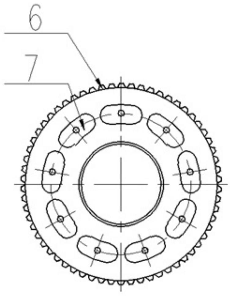
[0029] A plurality of oil through holes are opened on the friction conversion disc, and the plurality of oil through holes are uniformly arranged in a ring shape, and each oil through hole corresponds to a slipper shoe.
[0030] The out...
Embodiment 2
[0034] Embodiment 2 provides a friction structure between a shoe and a support plate, including a shoe 1, a friction conversion plate 3, a support plate 4 and a cage 2; the cage is used to hold the shoe;
[0035] The friction transformation disc is arranged between the sliding shoe and the support disc;
[0036] forming a connection from the outer edge of the cage to the outer edge of the friction conversion disk, so that the cage and the friction conversion disk can rotate integrally;
[0037] The disk surface of the friction transformation disk corresponding to the support disk is the friction surface; the disk surface of the friction transformation disk corresponding to the sliding shoe is the holding surface 9;
[0038] A plurality of oil through holes are opened on the friction conversion disc, and the plurality of oil through holes are uniformly arranged in a ring shape, and each oil through hole corresponds to a slipper shoe.
[0039] The outer edge of the friction con...
PUM
 Abstract
Description
Claims
Application Information