Safe Internet of Things monitoring equipment

A technology of monitoring equipment and the Internet of Things, which is applied in the direction of mechanical equipment, TVs, color TV parts, etc., can solve the problems of long steel pipes, inconvenient camera adjustments, additional tools for maintenance personnel, etc., to achieve height reduction and shooting angles Convenience, easy and fast maintenance effect

Pending Publication Date: 2022-02-15
雷华
6 Cites 0 Cited by

AI-Extracted Technical Summary

Problems solved by technology

[0003] In daily life, IoT monitoring equipment is used for community monitoring to record the flow of people and vehicles. In the prior art, IoT monitoring equipment is mostly fixed in the following way: fix the steel pipe on the ground, and then install the camera on the top ...

Method used

[0038] In the present embodiment, by installing a bearing at the end of the drive shaft 13, the contact between the drive shaft 13 and the inner wall of the power ring 15 is prevented, and the wear of the drive shaft 13 is prevented. After a long time of use, the drive shaft 13 shakes.
[0040] In the present embodiment, because the force between the rotating shaft ...

Abstract

The invention relates to the technical field of monitoring accessory devices, in particular to safe Internet of Things monitoring equipment. According to the equipment, a structure is simple, height of a camera is easy to adjust, a shooting angle of the camera is convenient to adjust, and use is more convenient. The safe Internet of Things monitoring equipment comprises a base, wherein four fixing holes are formed in edge areas of the base in a circumferential array mode, a cylindrical positioning column is fixed to the base, and a sleeve is coaxially and rotationally installed on the positioning column; and a first door-shaped plate is fixed to the top end of the sleeve, a first rotating shaft is rotationally installed on the door-shaped plate, and a second rotating shaft is fixed to the door-shaped plate. The equipment further comprises a second door-shaped plate, a first driving rod and a second driving rod, wherein a third rotating shaft and a fourth rotating shaft are fixedly installed on the second door-shaped plate, two ends of the first driving rod are rotationally connected with the second rotating shaft and the fourth rotating shaft respectively, one end of the second driving rod is fixedly connected with the first rotating shaft, and the other end of the second driving rod is rotationally connected with the third rotating shaft; and a swing arm is fixed to one end of the first rotating shaft, and a driving shaft is fixed to the other end of the swing arm.

Application Domain

Television system detailsColor television details +1

Technology Topic

Internet of ThingsStructural engineering +3

Image

  • Safe Internet of Things monitoring equipment
  • Safe Internet of Things monitoring equipment
  • Safe Internet of Things monitoring equipment

Examples

  • Experimental program(1)

Example Embodiment

[0023] The specific implementation manners of the present invention will be further described in detail below in conjunction with the accompanying drawings and embodiments. The following examples are used to illustrate the present invention, but are not intended to limit the scope of the present invention.
[0024] In the description of the present invention, it should be noted that unless otherwise specified and limited, the terms "installation" and "connection" should be understood in a broad sense, for example, it can be a fixed connection, a detachable connection, or an integral Ground connection; it can be a mechanical connection or an electrical connection; it can be a direct connection or an indirect connection through an intermediary, and it can be the internal communication of two components. Those of ordinary skill in the art can understand the specific meanings of the above terms in the present invention in specific situations.
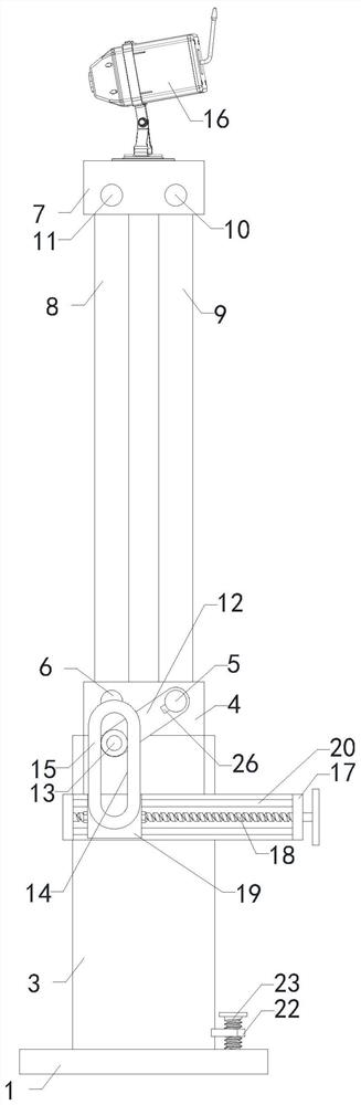
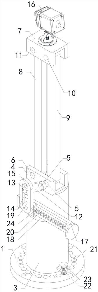
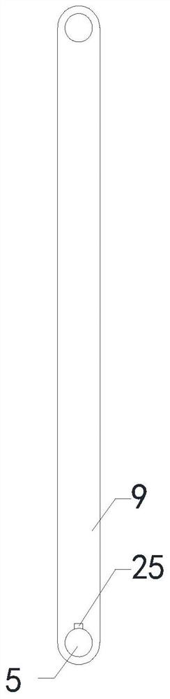
[0025] like Figure 1 to Figure 4 As shown, a security-type Internet of Things monitoring device of the present invention includes: a base 1, four fixing holes are arranged in a circular array in the edge area of ​​the base 1, and a cylindrical positioning column 2 is fixed on the base 1, and the positioning column 2 A sleeve 3 is installed on the upper coaxial rotation;
[0026] The top of the casing 3 is fixed with a gate plate one 4, a rotating shaft one 5 is installed on the gate plate, and a rotating shaft two 6 is fixed on the gate plate, which also includes a gate plate two 7, a driving rod one 8 and a driving rod two 9. Rotating shaft 3 10 and rotating shaft 4 11 are fixedly installed on door type plate 2 7, the two ends of driving rod 1 8 are respectively connected to rotating shaft 2 6 and rotating shaft 4 11, and one end of driving rod 2 9 is fixedly connected to rotating shaft 1 5 , the other end of the driving rod two 9 is rotationally connected with the rotating shaft three 10;
[0027] One end of the rotating shaft 5 is fixed with a swing arm 12, the other end of the swing arm 12 is fixed with a drive shaft 13, the casing 3 is fixed with a drive mechanism, and the output end of the drive mechanism is fixed with a power ring 15 with a long hole 14 , the drive shaft 13 passes through the power ring 15;
[0028] A camera main body 16 is installed on the top of the door type plate 2 7;
[0029] In this embodiment, during normal use, use screws to pass through the fixing holes on the base 1 to fix the base 1 and the positioning column 2, and then rotate the sleeve 3 and other components on the positioning column 2, when the camera body needs to be adjusted 16 When performing maintenance, operate the driving mechanism to move the power ring 15 in the horizontal direction. Since the rotating shaft 15 is rotationally connected to the door panel 4, the swing arm 12 is fixedly connected to the rotating shaft 15, and the drive fixed at the end of the swing arm 12 The shaft 13 passes through the elongated hole 14 on the power ring 15, so that the power ring 15 moving to the right makes the swing arm 12, the drive shaft 13, the rotating shaft one 5 and the driving rod one 8 all rotate around the rotating shaft one 5 as the axis. Under the cooperation of rotating shaft one 5, rotating shaft two 6, rotating shaft three 10 and rotating shaft four 11, driving rod one 8, driving rod two 9, door type plate one 4 and door type plate two 7 form a parallelogram structure, thereby with rotating shaft one 5 The driving rod one 8 rotating for the axis makes the door panel two 7 and the camera main body 16 thereon rotate, and the angle of the camera main body 16 is constant, thereby reducing the height of the camera main body 16, which is more convenient and quick when maintenance is carried out.
[0030] A kind of safe Internet of things monitoring equipment of the present invention, driving mechanism comprises door type plate 3 17 that is connected with casing 3, and door type plate 3 17 is rotatably installed with screw rod 18, and screw rod 18 is threadedly connected with moving block 19, Two guide rods 20 passing through the moving block 19 are also fixed on the door type plate three 17, and the moving block 19 is fixedly connected with the power ring 15;
[0031] One end of screw mandrel 18 is equipped with handwheel;
[0032] In this embodiment, the screw mandrel 18 is rotated by rotating the hand wheel. Since the screw mandrel 18 is threadedly connected with the moving block 19, the moving block 19 cannot rotate under the action of the two guide rods 20, so the rotating hand wheel makes the moving block 19 And the power ring 15 moves, and because it is threaded drive, after the handwheel stops rotating, the moving block 19 has self-locking property.
[0033] In the security type Internet of Things monitoring device of the present invention, several adjustment holes 21 are opened in a circular array on the base 1, a support plate 22 is fixed on the casing 3, and a bolt 23 is threaded on the support plate 22, and the other end of the bolt 23 Extend into one of the adjustment holes 21;
[0034] In this embodiment, when the shooting angle of the camera body 16 needs to be adjusted, the bolt 23 is first separated from the adjustment hole 21, then the sleeve 3 is held and rotated, and then the bolt 23 is inserted into the nearest adjustment hole 21 to fix the sleeve 3 and the angle of the camera.
[0035] In the safety-type Internet of Things monitoring device of the present invention, the driving mechanism further includes two nuts 24, both of which are threadedly connected to the screw rod 18, and the two nuts 24 are respectively located on both sides of the moving block 19;
[0036] In this embodiment, after the height adjustment of the camera body 16 is completed, in order to prevent the camera body 16 from moving, two nuts 24 are rotated to closely contact the moving block 19 .
[0037] In the safety Internet of Things monitoring device of the present invention, a bearing is installed at the end of the drive shaft 13, and the outer ring of the bearing is in contact with the inner wall of the elongated hole 14;
[0038] In this embodiment, by installing a bearing at the end of the drive shaft 13, the contact between the drive shaft 13 and the inner wall of the power ring 15 is avoided to prevent the drive shaft 13 from being worn out, and the drive shaft 13 is shaken after long-term use.
[0039] A safety type Internet of Things monitoring device of the present invention, a key 25 is installed between the first rotating shaft 5 and the second driving rod 9;
[0040] In this embodiment, since the force between the rotating shaft one 5 and the driving rod two 9 is relatively large, a key one 25 is installed between them to prevent the rotating shaft one 5 and the driving rod two 9 from rotating relative to each other.
[0041] A safety Internet of Things monitoring device of the present invention, the moving block 19 is welded to the power ring 15;
[0042] In this embodiment, the connection reliability between the moving block 19 and the power ring 15 is improved.
[0043] In the security IoT monitoring device of the present invention, a key 2 26 is installed between the swing arm 12 and the rotating shaft 1 5 .
[0044] In this embodiment, the relative rotation between the swing arm 12 and the first rotating shaft 5 is prevented by installing the second key 26 between the swing arm 12 and the first rotating shaft 5 .
[0045] The above is only a preferred embodiment of the present invention, it should be pointed out that for those of ordinary skill in the art, without departing from the technical principle of the present invention, some improvements and modifications can also be made, these improvements and modifications It should also be regarded as the protection scope of the present invention.

PUM

no PUM

Description & Claims & Application Information

We can also present the details of the Description, Claims and Application information to help users get a comprehensive understanding of the technical details of the patent, such as background art, summary of invention, brief description of drawings, description of embodiments, and other original content. On the other hand, users can also determine the specific scope of protection of the technology through the list of claims; as well as understand the changes in the life cycle of the technology with the presentation of the patent timeline. Login to view more.

Similar technology patents

Medical care roasting lamp

Owner:CHENGDU GERUISI CULTURAL COMM

Dwarf type cover carriage

InactiveCN101003843Alower the altitudesmall maximum height
Owner:WISDRI ENG & RES INC LTD

Pest repelling device

ActiveCN1918982Alower the altitudeincrease contact length
Owner:SAKUDORY JAPAN

Variable-paddle type vertical axis wind turbine

InactiveCN102767477Alower the altitudegood for air traffic
Owner:杜满河

Polarizer and display panel

InactiveCN112433288Alower the altitudeavoid air bubbles
Owner:WUHAN CHINA STAR OPTOELECTRONICS SEMICON DISPLAY TECH CO LTD

Classification and recommendation of technical efficacy words

  • lower the altitude
  • Easy to maintain

Open-type full-face rock ripper

ActiveCN103437775Alower the altitudelarge working space
Owner:CHINA RAILWAY ENGINEERING EQUIPMENT GROUP CO LTD

Fine metal powder atomizing spray nozzle with molten metal easily flowing out

ActiveCN102837001AImprove atomization efficiencylower the altitude
Owner:HUNAN HENGJI POWDER TECH

Device for measuring flatness and parallelism of disc parts

Owner:INST OF MACHINERY MFG TECH CHINA ACAD OF ENG PHYSICS

Plasma display panel and its driving method

InactiveUS20050088369A1easy to maintain
Owner:PIONEER CORP

Method of positioning problem regions covered with indoor wireless network

ActiveUS20160337888A1accuracy be guaranteeeasy to maintain
Owner:RANPLAN WIRELESS NETWORK DESIGN

Detachable lamp holder of LED lamp

InactiveUS20110235320A1easy to maintain
Owner:HONEYWELL LONON ELECTRICAL SYST TECH GUANGDONG
Why Eureka
Try Eureka