
Mobile-cowl thrust reverser comprising thrust-reduction mechanism that is independent of mobile cowl

A thrust reverser, thrust reversal technology, applied in engine control, engine function, machine/engine, etc., can solve problems such as not allowing safe adjustment of propulsion components, large aerodynamic effects of deploying the reverser, etc. The effect of alleviating airspace congestion, reducing fuel consumption and reducing thrust

Pending Publication Date: 2022-02-15
SAFRAN NASEL +1
View PDF2 Cites 0 Cited by
  • Summary
  • Abstract
  • Description
  • Claims
  • Application Information

AI Technical Summary

Problems solved by technology

[0011] More generally, partial deployment of conventional thrust reversers does not allow safe regulation of the thrust of the propulsion assembly, especially when the propulsion assembly includes a jet engine with a high bypass ratio, due to which the aerodynamics of deploying the reverser particularly large effect

Method used


Image

  • Mobile-cowl thrust reverser comprising thrust-reduction mechanism that is independent of mobile cowl
  • Mobile-cowl thrust reverser comprising thrust-reduction mechanism that is independent of mobile cowl
  • Mobile-cowl thrust reverser comprising thrust-reduction mechanism that is independent of mobile cowl

Examples


Embodiment Construction

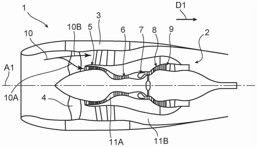
[0041] exist figure 1 In , an aircraft propulsion assembly 1 comprising a turbine engine 2 rectified by a nacelle 3 is shown. In this example, the turbine engine 2 is a twin-body twin-flow jet engine.

[0042] In the following, the terms "upstream", "downstream", "front" and "rear" are defined with respect to the direction D1 of the air flow through the propulsion assembly 1 when the propulsion assembly 1 is propelled.

[0043]The jet engine 2 has a longitudinal central axis A1, the various components of the jet engine, in this case from upstream to downstream of the jet engine 2, the fan 4, the low pressure compressor 5, the high pressure compressor 6, the combustion chamber 7, the high pressure turbine 8 and the low pressure The turbine, 9, extends around this longitudinal central axis. The compressors 5 and 6, the combustor 7 and the turbines 8 and 9 form a gas generator.

[0044] Normally, during operation of such a jet engine 2, an air flow 10 enters the propulsion as...


PUM


Abstract

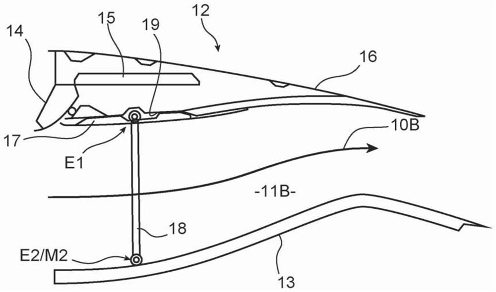
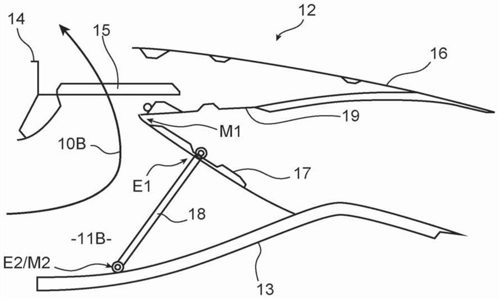
The invention relates to a thrust reverser (12) for an aircraft propulsion unit, the thrust reverser (12) comprising an internal fixed structure (13), a mobile cowl (16) and blocking flaps (17). The thrust reverser (12) comprises a first actuation mechanism that is configured to move the mobile cowl (16) between a closing position and an opening position so as to cause the blocking flaps (17) to move respectively between a retracted position and a deployed position, thus causing the thrust reverser (12) to pass respectively between a full-thrust configuration and a thrust-reversal configuration. The thrust reverser (12) comprises a second actuation mechanism that is configured to move the blocking flaps (17) between the retracted position and a partially deployed position when the mobile cowl (16) is in the closing position, so as to cause the thrust reverser (12) to pass respectively between the full-thrust configuration and a reduced-thrust configuration.

Description

technical field [0001] The present invention relates to the field of thrust reversers for aircraft propulsion assemblies, and more particularly to the field of thrust reversers of the cascade type. Background technique [0002] As a general rule, thrust reversers may be arranged in a straight-jet configuration to enable the propulsion assembly to generate thrust, and may be arranged in a reverse-jet or thrust-reversal configuration in which a portion of the gas circulating in the propulsion assembly is redirected to the front of the propulsion assembly, thereby generating aircraft braking reverse thrust. [0003] Cascade thrust reversers are usually installed in propulsion assemblies with twin-flow jet engines. In such a propulsion assembly, the primary flow circulates in a primary jet channel through a jet engine gas generator, and the secondary flow circulates in a secondary jet channel surrounding the gas generator. [0004] Most cascade thrust reversers, such as that d...

Claims


Application Information

Patent Timeline
Patent Type & Authority Applications(China)
IPC IPC(8): F02K1/72F02K1/76
CPCF02K1/72F02K1/763F05D2240/129F05D2260/50F05D2260/57F05D2270/051Y02T50/60
Inventor 丹尼·格卢瓦佛罗伦萨·马蒂厄·雅克·诺贝伦路易吉·比桑蒂
Owner SAFRAN NASEL
Learn More