Multi-point fixing device suitable for PICC catheterization and arteriopuncture catheterization
A technology of arterial puncture and multi-point fixation, which is applied in the field of medical assistance, can solve problems such as long time, and achieve the effect of reducing workload, reducing workload, and reducing the difficulty of fixation
- Summary
- Abstract
- Description
- Claims
- Application Information
AI Technical Summary
Problems solved by technology
Method used
Image
Examples
Embodiment 1
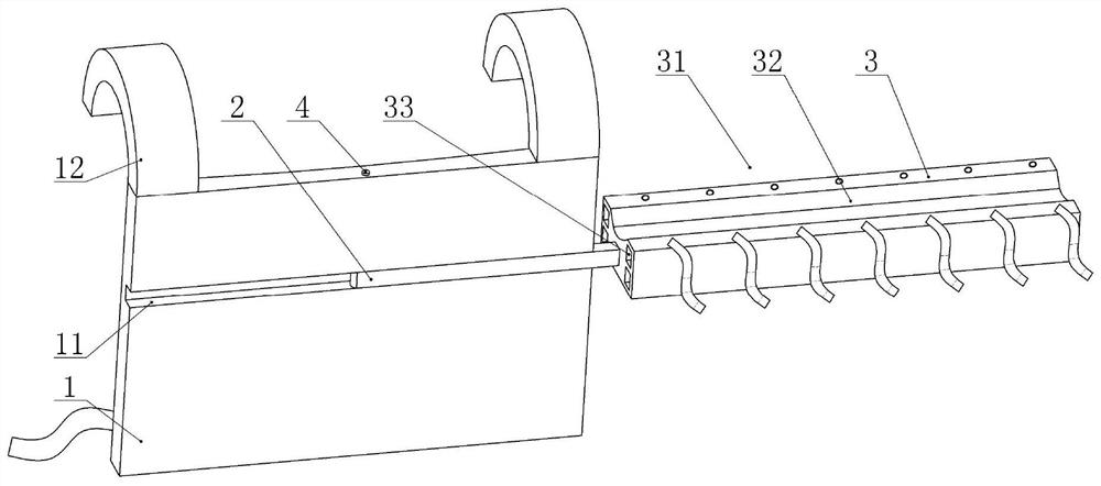
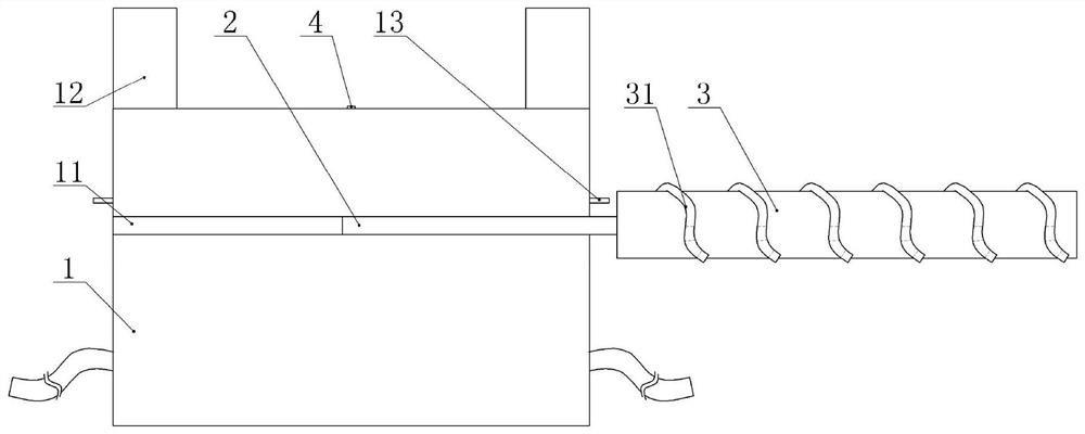
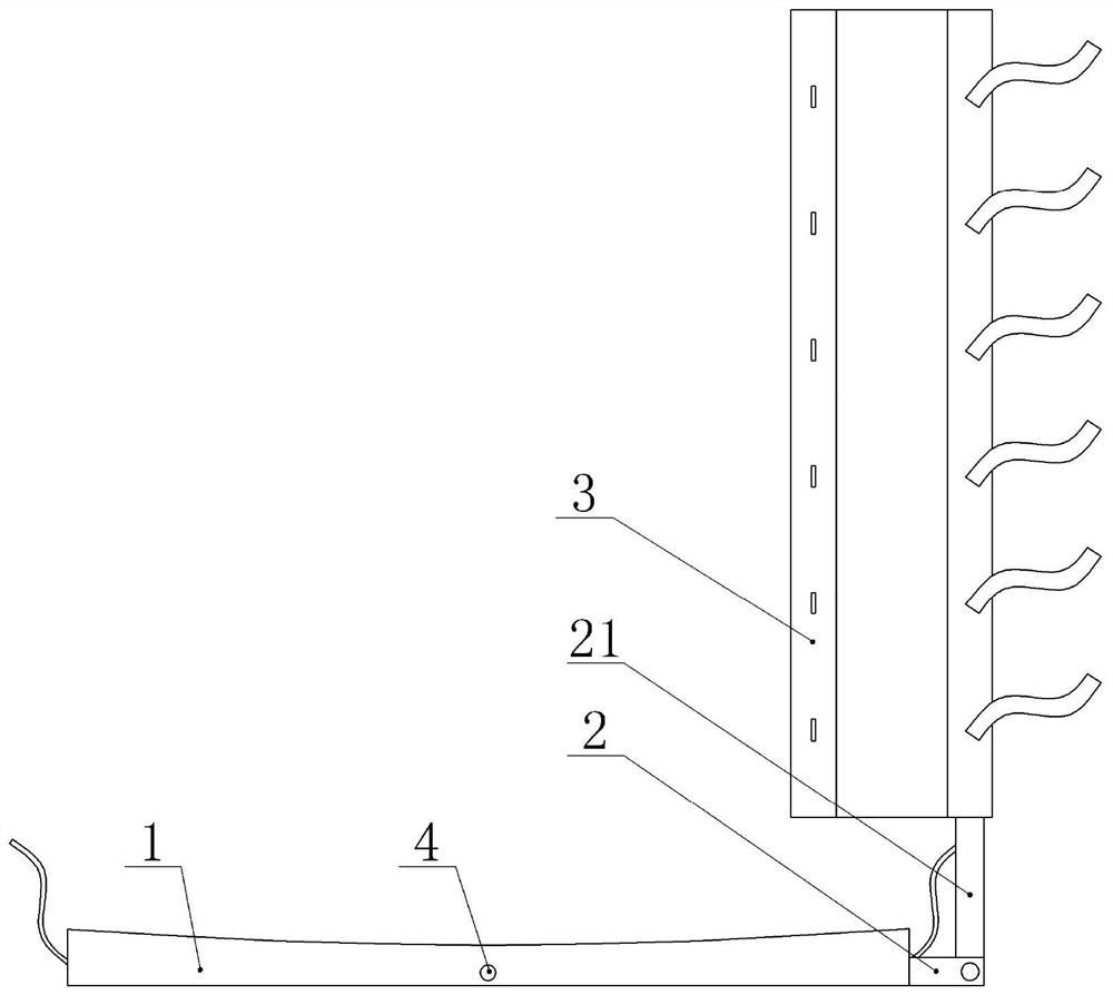
[0041] A multi-point fixation device suitable for PICC catheterization and arterial puncture catheterization, such as figure 1 with figure 2As shown, it includes a main body 1 and a fixed block 3. The rear side wall of the main body 1 is attached to the patient's back, and the cross section of the rear side wall of the main body 1 is arc-shaped, which can better fit the patient's back; the main body 1 Two first laces are fixed on the rear side wall of the main body 1 through pin shafts, and the two first laces are respectively located at the left and right ends of the main body 1. In actual implementation, the ends of the two first laces away from the main body 1 are fixed by needle and thread There is Velcro, the two first straps are connected by Velcro. Two arc-shaped plates 12 are welded on the top of the main body 1, and the vertical projections of the two arc-shaped plates 12 are respectively located at the left and right ends of the main body 1, and the longitudinal se...
Embodiment 2
[0052] On the basis of Example 1, such as Figure 4 As shown, the left end of the first rod body 2 in this embodiment is welded with the installation block 14 , and the connection position between the first rod body 2 and the installation block 14 is located at the lower end of the installation block 14 . The mounting block 14 is vertically provided with a second passage, and the lower end of the rotating shaft 4 passes through the mounting block 14; the upper end of the mounting block 14 is provided with a first passage, such as Figure 5 As shown, after the mounting block 14 is rotated by 90°, the bottom of the rotating shaft 4 passes through the first channel to position the mounting block 14, and at this time, a limiting space is formed between the first rod body 2 and the first channel.
[0053] The right side of mounting block 14 is provided with U-shaped block 6, combines Image 6 As shown, the end of the U-shaped block 6 is integrally formed with a block 61, and the w...
Embodiment 3
[0056] On the basis of embodiment 1 or embodiment 2, such as Figure 7 As shown, the main body 1 in this embodiment includes a left half body and a right half body. The right wall of the left half body and the left wall of the right half body are integrally formed with a plurality of sawtooth blocks, and the vertical gaps of the plurality of sawtooth blocks are distributed. , and the sawtooth blocks on the left half and the right half mesh with each other, the shaft 4 passes through the aligned sawtooth blocks vertically and is screwed with the bottom sawtooth block, and the left half and the right half are connected through the shaft 4 . In actual implementation, multiple rotating shafts 4 are provided to improve the fixing effect on the sawtooth portion.
[0057] Such as Figure 8 As shown, the thickness of the sawtooth part on the left half body gradually decreases from left to right, and the thickness of the sawtooth part on the right half body gradually increases from l...
PUM
 Abstract
Description
Claims
Application Information
 - R&D
- Intellectual Property
- Life Sciences
- Materials
- Tech Scout
- Unparalleled Data Quality
- Higher Quality Content
- 60% Fewer Hallucinations
Browse by: Latest US Patents, China's latest patents, Technical Efficacy Thesaurus, Application Domain, Technology Topic, Popular Technical Reports.
© 2025 PatSnap. All rights reserved.Legal|Privacy policy|Modern Slavery Act Transparency Statement|Sitemap|About US| Contact US: help@patsnap.com


