Workpiece spraying device

A technology for spraying devices and workpieces, which is applied in the direction of spraying devices, devices for coating liquid on the surface, coatings, etc. It can solve the problems of endangering the health of workers, inability to spray, and uneven spraying, etc., to improve the efficiency of spraying processing, Improve the effect of spraying and uniform coating

Pending Publication Date: 2022-02-18
苏州奥梦电器股份有限公司
View PDF0 Cites 1 Cited by
  • Summary
  • Abstract
  • Description
  • Claims
  • Application Information

AI Technical Summary

Problems solved by technology

[0003] The spraying devices currently on the market can be divided into manual spraying equipment and automatic spraying equipment according to the degree of automation. The manual spraying method has the defects of low work efficiency and uneven spraying, and most of the sprayed materials have pungent odors, which endanger the health of workers. Health; when the automatic spraying setting is in use, the protective box plays a protective role for the staff. The nozzle can be moved under the action of the driving device to spray the surface of the workpiece, but the workpiece is usually placed directly on the working platform, so that the back of the workpiece It cannot be sprayed, and it is necessary for the staff to turn the workpiece over to achieve all-round spraying on the surface of the workpiece, which cannot ensure the health of the operator and reduces the spraying production efficiency of the workpiece. In addition, the existing spraying device only has Spraying function, no auxiliary drying function, in order to avoid damage to the surface coating of the workpiece, the workpiece after spraying needs to be dried for a certain period of time before it can be taken out, which further reduces the spraying processing efficiency of the workpiece

Method used


Image

  • Workpiece spraying device
  • Workpiece spraying device
  • Workpiece spraying device

Examples


Embodiment Construction

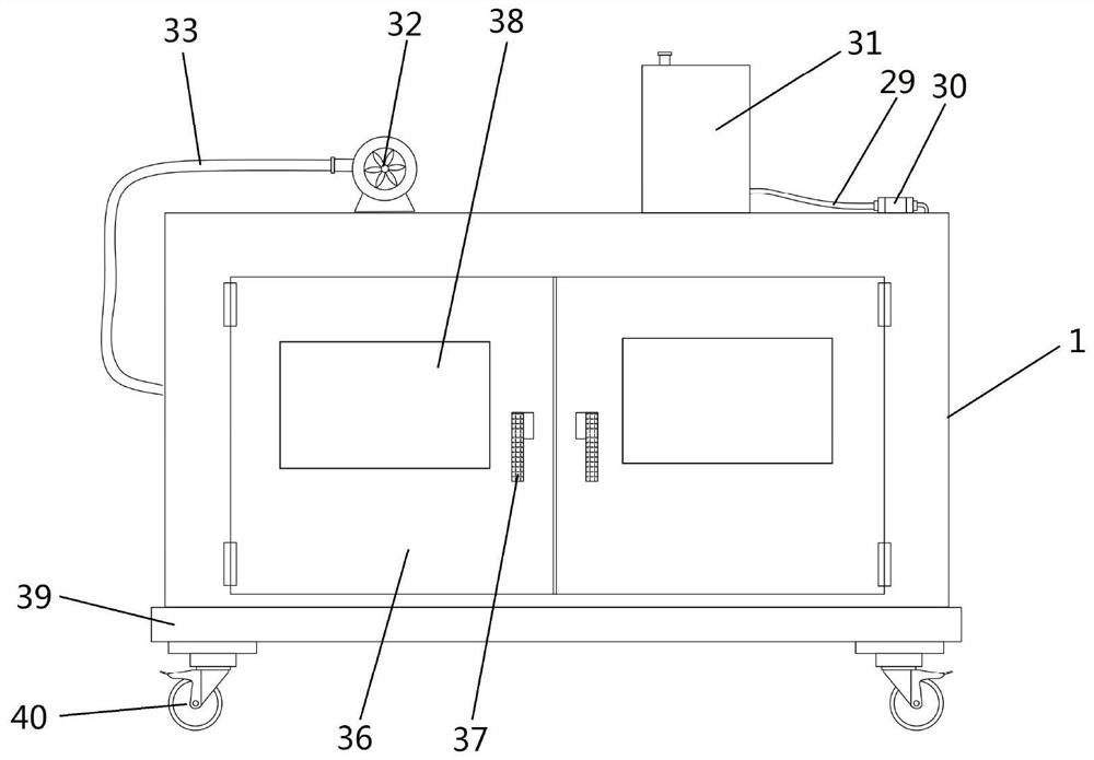
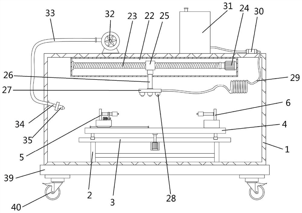
[0025] Embodiments of the present invention disclose a workpiece spraying device, such as Figure 1 to Figure 6 As shown, it includes a housing 1, a support frame body 2 is provided at the inner bottom of the housing 1, a supporting plate 3 is installed on the top of the supporting frame body 2, a rotating drive mechanism is provided on the top of the supporting plate 3, and a spraying platform 4 is provided on the rotating driving mechanism. , the rotary drive mechanism can drive the spraying platform 4 to rotate in the horizontal plane, and the opposite sides of the top of the spraying platform 4 are respectively provided with a first clamping assembly 5 and a second clamping assembly 6 for clamping and fixing the two ends of the workpiece, the first clamping The holding assembly 5 can drive the clamped workpiece to turn over and rotate along the axis under the action of the turning mechanism 13. A transmission box 22 is installed at the middle position of the top inside the ...


PUM


Abstract

The invention discloses a workpiece spraying device which comprises a shell, a supporting frame body is arranged at the bottom in the shell, a supporting plate is installed at the top of the supporting frame body, a rotary driving mechanism is arranged at the top of the supporting plate, a spraying platform is arranged on the rotary driving mechanism, and the rotary driving mechanism can drive the spraying platform to rotate on the horizontal plane. A first clamping assembly and a second clamping assembly which are used for clamping and fixing the two ends of a workpiece are arranged on the two opposite sides of the top of the spraying platform correspondingly, the first clamping assembly can drive the clamped workpiece to turn over and rotate along the axis under the action of a turn-over mechanism, and a transmission box is installed in the middle of the top in the shell. A transmission mechanism is arranged in the transmission box, an electric telescopic rod is arranged on the transmission mechanism, the transmission mechanism can drive the electric telescopic rod to move transversely, the bottom of the electric telescopic rod penetrates through the bottom of the transmission box and is connected with a liquid spraying pipe located below the transmission box, a plurality of spraying heads are evenly installed at the bottom of the liquid spraying pipe, and an air blowing mechanism is arranged on the inner side wall of the shell.

Description

technical field [0001] The invention relates to the technical field of workpiece spraying processing equipment, in particular to a workpiece spraying device. Background technique [0002] The spraying device is a special equipment for covering the surface of metal or non-metal workpieces with a protective layer or a decorative layer. It is a product in an environment where automation is becoming more and more common with the development of industrial technology. With the increasing degree of automation, the spraying production line The application of the technology is becoming more and more extensive, and penetrates into many fields of the national economy. [0003] The spraying devices currently on the market can be divided into manual spraying equipment and automatic spraying equipment according to the degree of automation. The manual spraying method has the defects of low work efficiency and uneven spraying, and most of the sprayed materials have pungent odors, which enda...

Claims


Application Information

Patent Timeline
Patent Type & Authority Applications(China)
IPC IPC(8): B05B16/20B05B13/02B05B13/04B05B14/40B05B15/68B05D3/04
CPCB05B16/20B05B13/0228B05B13/041B05B15/68B05B14/40B05D3/0406
Inventor 严雨
Owner 苏州奥梦电器股份有限公司
Why Eureka
Try Eureka