Spraying equipment for spherical parts with auxiliary positioning structure for general machinery

An auxiliary positioning and general-purpose mechanical technology, which is applied in the direction of spraying devices, can solve the problems of reducing the spraying efficiency of parts, uneven spraying on the surface of spherical parts, and the inability to assist the limit of spherical parts, so as to improve the efficiency of spraying processing and avoid uneven spraying Effect

Active Publication Date: 2022-01-25
HUANGHE JIAOTONG UNIV
View PDF9 Cites 0 Cited by
  • Summary
  • Abstract
  • Description
  • Claims
  • Application Information

AI Technical Summary

Problems solved by technology

[0005] The object of the present invention is to provide a kind of spherical parts spraying equipment with auxiliary positioning structure for general machinery, to solve the problem that most of the existing spherical parts spraying equipment for general machinery proposed in the background technology cannot be used for spherical parts during use. Auxiliary limit, so that the parts are easy to drop during the spraying process, resulting in collision damage on the surface of the parts, affecting the quality of the finished parts processed, and reducing the spraying efficiency of the parts, and using a general clamping device to assist spherical parts When the position is limited, in the process of spraying, it is easy to have uneven spraying on the surface of spherical parts, and the existing spherical parts spraying equipment for general machinery cannot adjust the angle of the nozzle during use, so that the surface of the parts can be sprayed When the thickness of the surface of the spherical part after spraying is inconsistent, it will affect the quality of spraying and reduce the applicability in actual use.

Method used


Image

  • Spraying equipment for spherical parts with auxiliary positioning structure for general machinery
  • Spraying equipment for spherical parts with auxiliary positioning structure for general machinery
  • Spraying equipment for spherical parts with auxiliary positioning structure for general machinery

Examples


Embodiment Construction

[0030] The following will clearly and completely describe the technical solutions in the embodiments of the present invention with reference to the accompanying drawings in the embodiments of the present invention. Obviously, the described embodiments are only some, not all, embodiments of the present invention. Based on the embodiments of the present invention, all other embodiments obtained by persons of ordinary skill in the art without making creative efforts belong to the protection scope of the present invention.

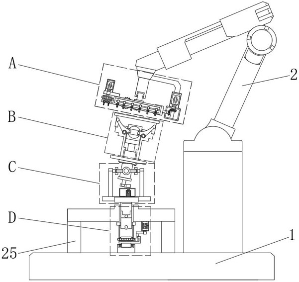
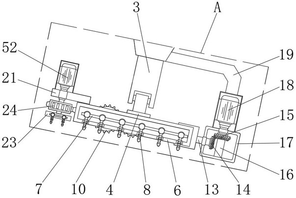
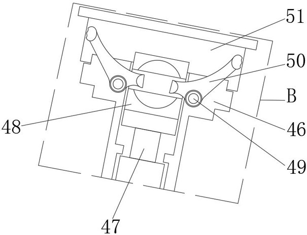
[0031] see Figure 1-11 , an embodiment provided by the present invention: a spherical parts spraying equipment with an auxiliary positioning structure for general machinery, including a base 1, a hydraulic telescopic rod 2, a first motor 9, a second motor 18, a third motor 32, a Four motors 37, pneumatic telescopic rod 47 and fifth motor 52, the top side of the base 1 is fixedly equipped with a hydraulic telescopic rod 2, and the end of the hydraulic telescop...


PUM


Abstract

The invention relates to the technical field of mechanical processing, in particular to a spherical part spraying equipment with an auxiliary positioning structure for general machinery, including a base, a hydraulic telescopic rod, a first motor, a second motor, a third motor, a fourth motor, a pneumatic telescopic Rod and the fifth motor, a hydraulic telescopic rod is fixedly installed on the top side of the base, and a first connecting rod is fixedly connected to the end of the hydraulic telescopic rod away from the base. The present invention is provided with a clamping rod, and by starting the fourth motor, the fourth motor drives the oblique rotation rod to rotate, so that the oblique rotation rod drives the rocker to take the first connecting shaft as the axis, so that the bottom end and the top end of the rocker are circular The movement makes it easy for the rocker to drive the spherical parts to shake inside the limit barrel, and it is convenient to spray the surface of the clamping rod comprehensively, avoiding uneven spraying on the surface of the spherical parts and affecting the quality of the spraying, and at the same time improving the spraying efficiency of the spherical parts.

Description

technical field [0001] The invention relates to the technical field of mechanical processing, in particular to a spherical part spraying equipment with an auxiliary positioning structure for general machinery. Background technique [0002] Spraying equipment is the product of an environment where automation is becoming more and more common with the development of industrial technology. With the increasing degree of automation, the application of spraying production lines is becoming more and more extensive, and it has penetrated into many fields of the national economy. Now The spraying equipment on the market can be divided into three types according to the degree of automation: manual spraying equipment, semi-automatic spraying equipment and fully automatic spraying equipment. [0003] Most of the existing spherical parts spraying equipment for general machinery cannot assist in the positioning of spherical parts during use, so that the parts are easy to drop during the sp...

Claims


Application Information

Patent Timeline
Patent Type & Authority Patents(China)
IPC IPC(8): B05B13/02B05B15/68
CPCB05B13/0221B05B15/68
Inventor 吴文明千志科夏运东李硕胡经飞
Owner HUANGHE JIAOTONG UNIV
Why Eureka
Try Eureka