Hardware punching machine tool

A stamping machine tool and hardware technology, applied in the direction of metal processing equipment, forming tools, manufacturing tools, etc., can solve the problems of wasting physical strength, wasting time, wasting time and personnel, and achieve the effect of avoiding manual replacement and simple equipment structure

Inactive Publication Date: 2022-02-18
丰烟兰
View PDF0 Cites 0 Cited by
  • Summary
  • Abstract
  • Description
  • Claims
  • Application Information

AI Technical Summary

Problems solved by technology

[0002] In the process of metal stamping processing, it is often used to use hydraulic pressure or a rotary cam to drive the punch to move up and down to realize metal stamping processing, but there are many problems in this process, first of all, in the process of stamping processing. Set the corresponding upper and lower molds in the area where the punch and parts are placed. Because the installation process of the upper and lower molds is complicated and needs to be replaced frequently, and the personnel also need to manually remove the screws that lock the mold when installing the mold. Locking, on the one hand, personnel need to waste a lot of time and effort to complete this task, on the other hand, the weight of the mold itself is relatively heavy, and the mold needs to be placed on the mold support. The great waste of physical strength makes the actual work efficiency of personnel not high, and it is precisely because of the existence of the above-mentioned shortcomings that the actual work efficiency of existing equipment is low

Method used


Image

  • Hardware punching machine tool
  • Hardware punching machine tool
  • Hardware punching machine tool

Examples


Embodiment Construction

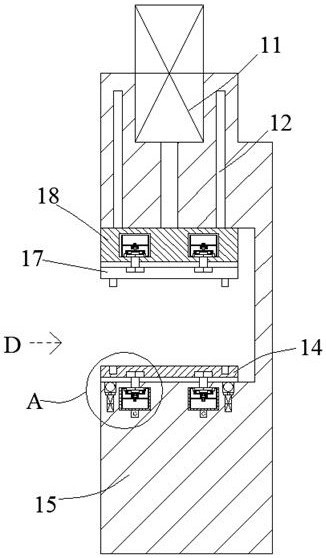
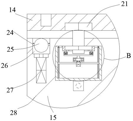
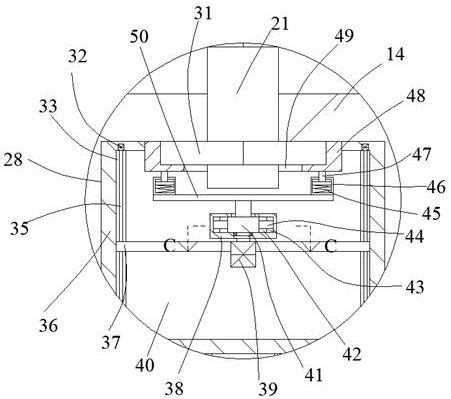
[0023] Such as Figure 1-Figure 6 As shown, the present invention is described in detail. For the convenience of description, the orientations mentioned below are now stipulated as follows: figure 1 The up, down, left, right, front and back directions of the projection relationship itself are consistent. A metal stamping machine tool of the present invention includes a body 15, and a protruding hydraulic cylinder 11 is arranged in the body 15, and a push rod side of the protruding hydraulic cylinder 11 is provided with a Matching block 18, one side of the matching block 18 is provided with a symmetrical guide rod 12, the guide rod 12 is slidingly fitted with the body 15, and the upper and lower sides of the inside of the body 15 and the matching block 18 are provided with symmetrical inner guide rods. Groove 28, the upper mold base 17 and the lower mold base 14 are respectively arranged inside the described interior, and a sliding fit box body 36 is provided for sliding in the...


PUM


Abstract

The invention discloses a hardware punching machine tool. The hardware punching machine tool comprises a machine body, wherein an extending hydraulic cylinder is arranged in the machine body; a matching block is arranged on one side of a push rod of the extending hydraulic cylinder; symmetrical guide rods are arranged on one side of the matching block; the guide rods are connected with the machine body in a sliding fit mode; symmetrical internal guide grooves are formed in an upper side and a lower side of the interior of the machine body and the matching block; an upper die base and a lower die base are arranged in the interior of the machine body; sliding matching box bodies are arranged in the internal guide grooves in a sliding mode; a box body inner cavity is formed in each sliding matching box body; a locking nut and a locking bolt are arranged in each box body inner cavity; the lower die base, the matching block and the sliding matching box bodies are locked through the locking nuts and the locking bolts; and a bottom sliding device facilitating sliding of the lower die base is arranged in the machine body. The hardware punching machine tool can achieve rapid replacement of dies by sliding the dies in T-shaped grooves, so that manual replacement by personnel is avoided.

Description

technical field [0001] The invention relates to the technical field of metal stamping equipment, in particular to a metal stamping machine tool. Background technique [0002] In the process of metal stamping processing, it is often used to use hydraulic pressure or a rotary cam to drive the punch to move up and down to realize metal stamping processing, but there are many problems in this process, first of all, in the process of stamping processing. Set the corresponding upper and lower molds in the area where the punch and parts are placed. Because the installation process of the upper and lower molds is complicated and needs to be replaced frequently, and the personnel also need to manually remove the screws that lock the mold when installing the mold. Locking, on the one hand, personnel need to waste a lot of time and effort to complete this task, on the other hand, the weight of the mold itself is relatively heavy, and the mold needs to be placed on the mold support. Th...

Claims


Application Information

Patent Timeline
Patent Type & Authority Applications(China)
IPC IPC(8): B21D37/14
CPCB21D37/14
Inventor 丰烟兰
Owner 丰烟兰
Why Eureka
Try Eureka