Eureka AIR delivers breakthrough ideas for toughest innovation challenges, trusted by R&D personnel around the world.

Junction OF A pylon WITH AN AIRCRAFT WING

A hanger and connecting part technology, applied in the direction of wings, aircraft parts, aircraft power devices, etc., can solve the problem of shortening the distance

Pending Publication Date: 2022-02-18
AIRBUS OPERATIONS SAS
View PDF0 Cites 0 Cited by
  • Summary
  • Abstract
  • Description
  • Claims
  • Application Information

AI Technical Summary

Problems solved by technology

The specific shape of the triangular connecting rods makes it impossible to further reduce this distance

Method used


Image

  • Junction OF A pylon WITH AN AIRCRAFT WING
  • Junction OF A pylon WITH AN AIRCRAFT WING
  • Junction OF A pylon WITH AN AIRCRAFT WING

Examples


Embodiment Construction

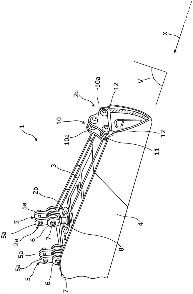
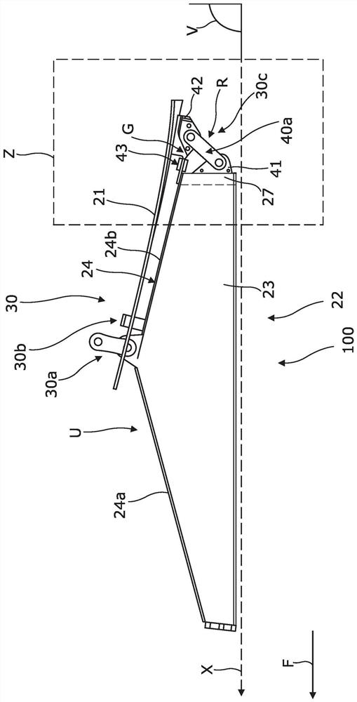
[0018] refer to figure 2 and Figure 5 , the connection part 100 between the pylon 22 and the wing 21 of the aircraft is established by the attachment member 30 . A pylon 22 is attached evenly below the wing 21 and is intended to support a jet engine (not shown) attached below the pylon 22 .

[0019] In the description, terminology relative to position refers to arrow F, which indicates the direction of advancement of wing 21 or pylon 22 through the air when subjected to the thrust provided by the jet engine.

[0020] As is known, the pylon 22 comprises a main structure 23 in the form of a rigid box extending in length from front to rear along a longitudinal axis X parallel to the forward direction F of the aircraft.

[0021] The longitudinal median plane V is the plane parallel to the longitudinal axis X and perpendicular to the ground (that is to say perpendicular to the horizontal plane) and dividing the main structure 23 into left and right parts.

[0022] The main str...


PUM


Abstract

A junction of a pylon with an aircraft wing, the pylon including a primary structure extending from front to rear along a longitudinal axis and in the form of a box with a rear face and an upper spar forming an upper face of the box, a longitudinal median plane separating the primary structure into two parts, left and right, the junction comprising a rear attachment system for attaching the pylon to the wing, this system being arranged at the rear of the primary structure, the rear attachment system including a shoe attached beneath the wing, the shoe being connected, via at least one articulated connecting rod, to a fitting attached to the rear face of the pylon by an articulation whose articulation pin, termed the horizontal articulation pin, is perpendicular to the longitudinal median plane, and the shoe being connected to the upper spar via a force reacting system. The force reacting system comprises an extension that extends the upper spar of the pylon towards the rear, and a spreader by which the shoe is hinged to the extension via the articulation, of which a hinge pin, called a vertical hinge pin, is parallel to the longitudinal mid-plane.

Description

technical field [0001] The invention relates to a connection part between a hanger and an aircraft wing. Background technique [0002] Conventionally, an aircraft comprises at least one jet engine attached under each of the aircraft's wings by means of a pylon consisting of a main structure in the form of a rigid box. The pylon is evenly attached under the wing by means for attaching the pylon to the wing. The attachment means consist of a front attachment system arranged substantially along half the length of the main structure, a rear attachment system arranged at the rear of the main structure, and an intermediate attachment arranged between the front and rear attachment systems System Components. [0003] refer to figure 1 , the front attachment system 2a on the upper spar 3 of the pylon 1 comprises two pairs of two-point connecting rods 5 arranged on either side of the longitudinal mid-plane V of the main structure 4, connecting the main The structure is divided int...

Claims


Application Information

Patent Timeline
IPC IPC(8): B64D27/18
CPCB64D27/18B64D27/12B64D27/402B64D27/40B64D27/404B64C3/32
Inventor 洛朗·弗雷诺奥利维尔·波蒂斯米夏埃尔·贝尔若托马斯·罗比利奥热尔曼·盖诺
Owner AIRBUS OPERATIONS SAS
Why Eureka
Eureka Blog
Learn More