Packaging film winding device with adjustable winding direction

A technology of winding direction and winding device, which is applied in the direction of object rotation and wrapping, which can solve the problems of inconvenient adjustment of winding direction and inconvenient

Active Publication Date: 2022-02-18
黄山源点新材料科技有限公司
View PDF6 Cites 1 Cited by
  • Summary
  • Abstract
  • Description
  • Claims
  • Application Information

AI Technical Summary

Problems solved by technology

[0005] The object of the present invention is to provide a packaging film winding device with adjustable winding direction, in order to solve the above background technology, the existing packaging film winding device is inconvenient to adjust Winding direction, at the same time it is inconvenient to fix the position of the film when adjusting the winding direction

Method used


Image

  • Packaging film winding device with adjustable winding direction
  • Packaging film winding device with adjustable winding direction
  • Packaging film winding device with adjustable winding direction

Examples


Embodiment 1

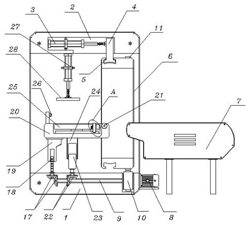
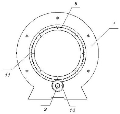
[0034] see Figure 1-7 Among them, including the body 1, an adjustment groove 2 is provided on the inner wall of the top of the body 1, and an adjustment rod 4 is connected to the adjustment groove 2 through a hydraulic rod 3, the bottom end of the adjustment rod 4 is located in the movable groove 5, and the movable groove 5 is opened On the outside of the winding ring 6, and the winding ring 6 is located in the body 1, and the side of the body 1 is equipped with a delivery seat 7; it also includes: a motor 8, the motor 8 is bolted to the bottom edge of the body 1, and the motor 8 The output end is connected with a guide post 9, and the guide post 9 is embedded and movably installed inside the bottom of the body 1. The front end of the guide post 9 is covered with a gear 10, and one end of the gear 10 protrudes from the inside of the body 1 and is arranged on the winding ring. 6, and the tooth block 11 is fixed at an equal angle at the corresponding position on the outside of ...

Embodiment 2

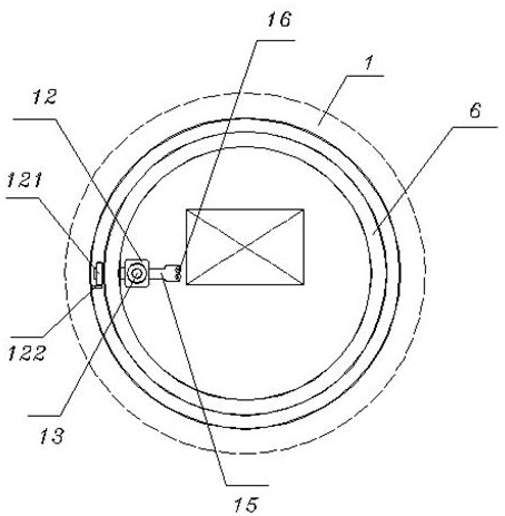
[0036] see figure 1 with Figure 3-4 Among them, the first bevel gear transmission assembly 17, the first bevel gear transmission assembly 17 is embedded in the bottom of the body 1, and one side of the first bevel gear transmission assembly 17 is provided with a second bevel gear transmission assembly 22, and the second bevel gear transmission assembly 22 Both the second bevel gear transmission assembly 22 and the first bevel gear transmission assembly 17 are sleeved on the guide post 9, the top of the first bevel gear transmission assembly 17 is connected with a reciprocating screw rod 18, and the reciprocating screw rod 18 is sleeved with a support rod 19, and the top of the support rod 19 is fixed with a winding table 20, and the top edge of the winding table 20 is embedded with a conveying roller 21, and the top of the second bevel gear transmission assembly 22 is connected with a movable bar 23, and the movable The top of the bar 23 is provided with a movable sleeve 24,...

Embodiment 3

[0038] see figure 1 with Figure 8-9 Among them, the edge of the coiling plate 25 is connected with a fixed rod 252 through the second spring 251, and the bottom of the fixed rod 252 is provided with a guide ring 253, and the guide ring 253 is fixed in the depression at the top of the coiling table 20, and the guide ring 253 The distribution position corresponds to the distribution position of the fixed rod 252, and the guide ring 253 is provided with a downward arc-shaped recessed area; when the coiled plate 25 rotates, it drives the fixed rod 252 to rotate, and cooperates with the restriction of the guide ring 253, so that the fixed The rod 252 can be ejected and fix the heat pressing and angle switching position of the packaging film, so as to avoid the packaging film falling off under tension during winding.


PUM


Abstract

The invention discloses a packaging film winding device with adjustable winding direction, and the device comprises a machine body, an adjusting groove is formed in the inner wall of the top of the machine body, an adjusting rod is connected into the adjusting groove through a hydraulic rod, the bottom end of the adjusting rod is located in a movable groove, and the movable groove is formed in the outer side of a winding ring; the device further comprises: a motor, which is fixed to the edge of the bottom of the machine body through bolts, wherein the front end of a guide column is sleeved with a gear, and a mounting frame is fixed to the side wall of the winding ring. and a first bevel gear transmission assembly, which is installed in the bottom of the machine body in an embedded mode, and has the top connected with a reciprocating lead screw, wherein the top of a second bevel gear transmission assembly is connected with a movable strip. According to the packaging film winding device with the adjustable winding direction, by adjusting the winding direction of a packaging film, multi-face winding can be conducted on a workpiece, meanwhile, when the direction of the winding film is adjusted, stable switching of the direction of the winding film is guaranteed, and falling off is avoided.

Description

technical field [0001] The invention relates to the technical field of packaging film winding, in particular to a packaging film winding device with adjustable winding direction. Background technique [0002] The packaging film is wrapped on the workpiece in the form of a film to protect the workpiece from waterproofing and anticorrosion. It is a conventional form of workpiece packaging. It has the characteristics of good tensile performance, high transparency, and strong retractability. The workpiece is automatically wound, which greatly improves the work efficiency, but the existing packaging film winding device has the following problems in use: [0003] When wrapping the workpiece through the packaging film, most of the outside of the workpiece needs to be fully wrapped. The existing packaging film winding device is inconvenient to adjust the winding direction, resulting in the need to stop the operation to wrap the other surface. At the same time, the existing packaging...

Claims


Application Information

Patent Timeline
Patent Type & Authority Applications(China)
IPC IPC(8): B65B11/04
CPCB65B11/04
Inventor 孙争光周乐金海勇方波俞宙卢磊磊
Owner 黄山源点新材料科技有限公司
Why Eureka
Try Eureka