Civil engineering deep foundation pit inclinometer base tube
A technology of civil engineering and inclinometer tubes, which is applied in basic structure engineering, basic structure tests, construction, etc., can solve problems affecting the accuracy of inclinometers and achieve high accuracy
- Summary
- Abstract
- Description
- Claims
- Application Information
AI Technical Summary
Problems solved by technology
Method used
Image

Examples
Embodiment 1
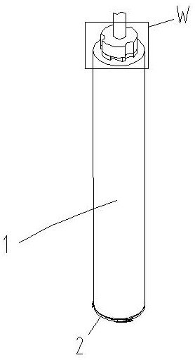
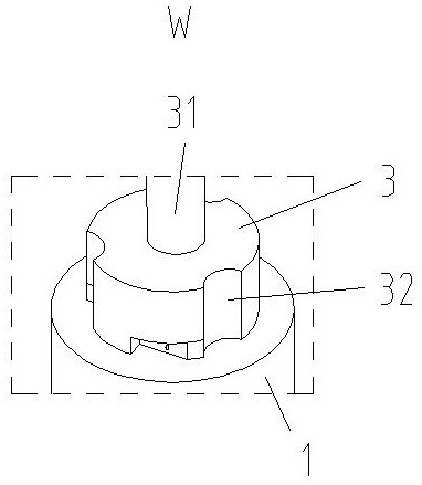
[0022] Such as Figure 1-Figure 5 As shown, the base pipe of a kind of inclinometer pipe for civil engineering deep foundation pit provided by the present invention includes a pipe body 1, in which an inclinometer pipe 10 is housed, and the top of the pipe body 1 is fixedly connected with a cover plate 3, and the cover plate 3 The upper end is provided with threading pipe 31, and threading pipe 31 is connected with pipe body 1, and the signal line of inclinometer pipe 10 passes through threading pipe 31, and the outer side of cover plate 3 is provided with a plurality of escape grooves 32, through avoidance groove 32 conveniently The pipe body 1 rotates.
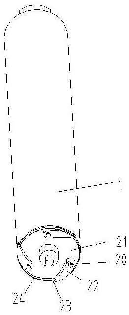
[0023] The bottom of the pipe body 1 is provided with a clamping device 2. The clamping device 2 includes a base plate 21 and a water-soluble paper tape 24. The base plate 21 is fixed on the lower end of the tube body 1. The lower side of the base plate 21 is fixedly connected to a plurality of fixed shafts 20. The fixed sha...
Embodiment 2
[0027] Such as Figure 1-Figure 10 As shown, the base pipe of a kind of inclinometer pipe for civil engineering deep foundation pit of the above-mentioned embodiment 1 is installed by hoisting equipment. The hoisting equipment includes a hoisting platform 4 and an extension pipe 6. Rotate and connect the drive ring 41 in the hole, the drive ring 41 is symmetrically provided with two threaded holes, each threaded hole is internally threaded to connect the insertion rod 42, and the outer side of the upper end of the extension tube 6 is provided with a jack 61, and the jack 61 corresponds to the insertion rod 42 Set, the hoisting platform 4 is fixedly connected to the driving motor 43, the main shaft of the driving motor 43 is fixedly connected to the gear 44, the outer side of the driving ring 41 is fixedly connected to the outer gear ring 45, the outer gear ring 45 is meshed with the gear 44, and the inner wall of the extension tube 6 lower end is provided with Sliding hole 62,...
PUM
 Abstract
Description
Claims
Application Information