
Rotary balance valve and rotary hydraulic system

A technology of balance valve and shuttle valve, which is applied in the direction of fluid pressure actuators, servo motors, servo motor components, etc., which can solve the problems of large impact on the stop of the rotary mechanism, inability to move the rotary mechanism, and difficulty in realizing it, so as to achieve the effect of reducing the impact

Pending Publication Date: 2022-02-22
SHANGHAI LUNLIAN ELECTROMECHANICAL EQUIP CO LTD
View PDF0 Cites 0 Cited by
  • Summary
  • Abstract
  • Description
  • Claims
  • Application Information

AI Technical Summary

Problems solved by technology

However, when the slewing mechanism is in motion, the relief valve needs a higher setting pressure, so as not to open the relief valve when the oil supply pressure is not enough to start the motor so that the slewing mechanism cannot move; when the slewing mechanism stops, the relief valve A lower set pressure is required to avoid excessive impact when the slewing mechanism stops. At this time, there is a contradiction between the two, which makes it difficult to realize the requirement of "high pressure start, low pressure brake".

Method used


Image

  • Rotary balance valve and rotary hydraulic system
  • Rotary balance valve and rotary hydraulic system
  • Rotary balance valve and rotary hydraulic system

Examples


Embodiment Construction

[0024] It can be seen from the background technology that the existing balance valve group is not stable enough when the slewing mechanism is running and stopping, and it is easy to cause impact on the hydraulic components.

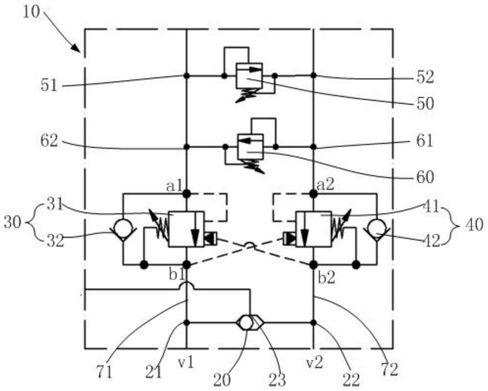
[0025] Now analyze in conjunction with a kind of balanced valve group 10, refer to figure 1 , the balance valve group 10 includes:

[0026] Shuttle valve 20, said shuttle valve 20 has a first shuttle valve inlet 21, a second shuttle valve inlet 22 and a shuttle valve outlet 23;

[0027] The first balance valve 30, the first balance valve 30 includes a first pressure valve 31 and a first one-way valve 32, the first pressure valve 31 has a first main working oil port a1, a first auxiliary working oil port b1 , the first one-way valve 32 is connected to the first main working oil port a1 and the first auxiliary working oil port b1;

[0028] The second balance valve 40, the second balance valve 40 includes a second pressure valve 41 and a second check valve...


PUM


Abstract

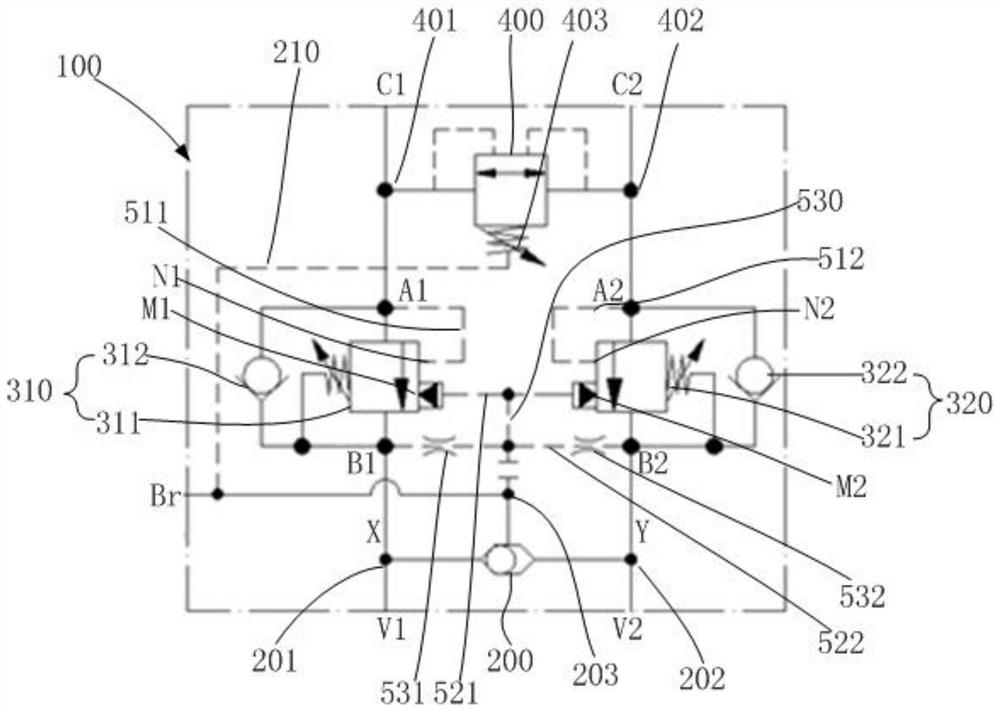
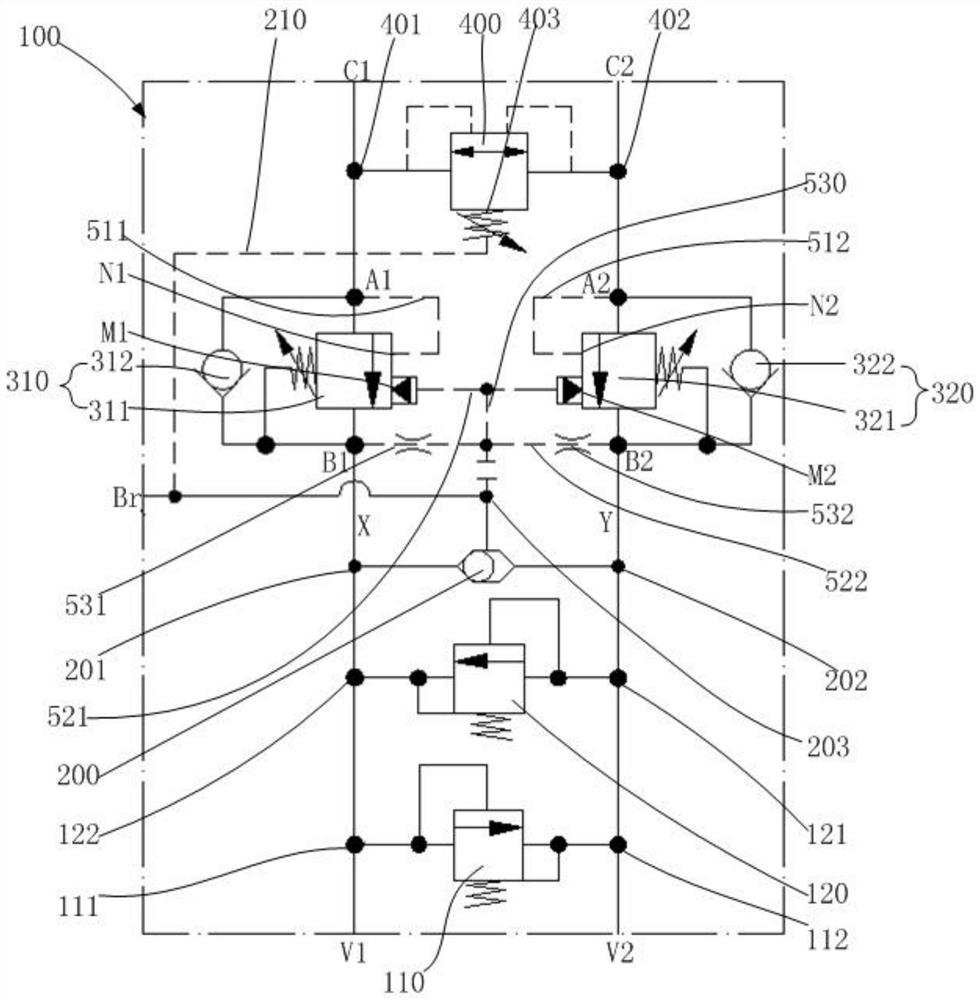
The invention discloses a rotary balance valve and a rotary hydraulic system, wherein the rotary balance valve comprises a shuttle valve, a first balance valve, a second balance valve, an overflow valve and an oil duct; the shuttle valve is provided with a first shuttle valve inlet, a second shuttle valve inlet and a shuttle valve outlet; the first balance valve is provided with a first main working oil port and a first auxiliary working oil port; the second balance valve is provided with a second main working oil port and a second auxiliary working oil port; the overflow valve comprises a first overflow port, a second overflow port and an overflow valve external control port, and the overflow valve external control port is communicated with a pressure spring in the overflow valve; the oil duct comprises a first main oil duct, a second main oil duct and a pressurizing oil duct, the first main oil duct is communicated with the first shuttle valve inlet, the first auxiliary working oil port, the first main working oil port and the first overflow port, the second main oil duct is communicated with the second shuttle valve inlet, the second auxiliary working oil port, the second main working oil port and the second overflow port, and the pressurizing oil duct is communicated with the shuttle valve outlet and the overflow valve external control port. The operation stability of the rotary balance valve is improved favourably, and the stopping softness of a rotary mechanism is improved.

Description

technical field [0001] The invention relates to the technical field of hydraulic control, in particular to a rotary balance valve and a rotary hydraulic system. Background technique [0002] In the field of construction machinery, the transmission mode of most working mechanisms is hydraulic transmission, that is, the engine drives the hydraulic pump to provide hydraulic energy, and the hydraulic control valve provides hydraulic cylinders or hydraulic motors with flow and maximum pressure for supporting actions, and then completes the realization of mechanical equipment. Actions. [0003] When the slewing mechanism of the equipment operates, it is powered by a hydraulic motor. Due to its large slewing inertia, the speed is often unstable during the action. When the slewing action is stopped, the impact is very large, which will have a very large impact on the equipment. harm. Therefore, a rotary balance valve must be used in the rotary hydraulic motor circuit to make its o...

Claims


Application Information

Patent Timeline
Patent Type & Authority Applications(China)
IPC IPC(8): F15B11/08F15B13/02
CPCF15B13/02F15B11/08F15B13/023
Inventor 陈智星孔晨菁
Owner SHANGHAI LUNLIAN ELECTROMECHANICAL EQUIP CO LTD
Learn More