
Dust treatment equipment for numerical control machining

A dust treatment and equipment technology, applied in metal processing equipment, metal processing machinery parts, manufacturing tools, etc., can solve problems such as unfavorable long-term use, bending and deformation of access ports, and achieve the effect of avoiding damage and quick connection

Inactive Publication Date: 2022-02-25
肖育龙
View PDF0 Cites 0 Cited by
  • Summary
  • Abstract
  • Description
  • Claims
  • Application Information

AI Technical Summary

Problems solved by technology

[0004] The purpose of the embodiments of the present invention is to provide a dust treatment equipment for numerical control machining, which aims to solve the problem that the position and angle of the dust inlet in the prior art are fixed, and when the dust connection ends with different positions and angles are matched, the inlet will be damaged. Bending deformation is not conducive to the problem of long-term use

Method used


Image

  • Dust treatment equipment for numerical control machining
  • Dust treatment equipment for numerical control machining
  • Dust treatment equipment for numerical control machining

Examples


Embodiment Construction

[0017] In order to make the object, technical solution and advantages of the present invention more clear, the present invention will be further described in detail below in conjunction with the accompanying drawings and embodiments. It should be understood that the specific embodiments described here are only used to explain the present invention, not to limit the present invention.

[0018] The specific implementation of the present invention will be described in detail below in conjunction with specific embodiments.

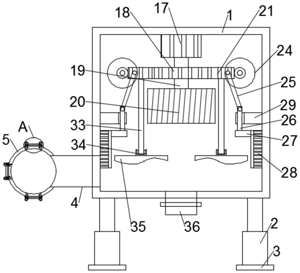
[0019] Such as figure 1 As shown, it is a structural diagram of a dust treatment equipment for numerical control machining provided by an embodiment of the present invention. The dust treatment equipment includes:

[0020] A dust collection box 1, the dust collection box 1 is installed on the foot 3 through a support member 2;

[0021] A dust inlet pipe 4, a joint 5 is installed on the dust inlet pipe 4, which is connected to the dust connection end;

[002...


PUM


Abstract

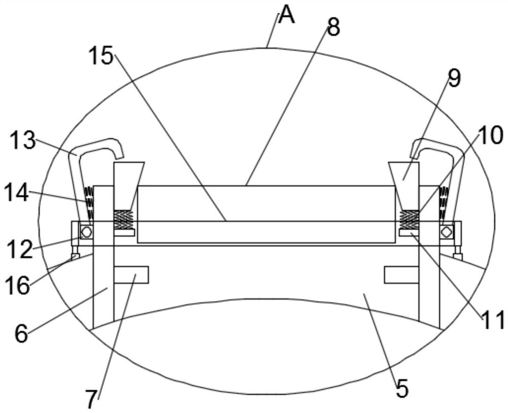
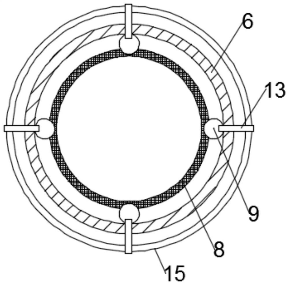
The invention is suitable for the technical field of numerical control machining, and provides dust treatment equipment for numerical control machining. The dust treatment equipment comprises a dust collection box which is mounted on a foot margin through a supporting piece, a dust inlet pipe and a dust suction mechanism, wherein a joint is mounted on the dust inlet pipe, and the dust inlet pipe is connected with the dust connecting end; the dust suction mechanism is mounted in the dust collection box and used for generating a suction force to suck dust; and the joint is connected with a plurality of quick joint mechanisms, and the directions of the quick joint mechanisms are different. A plurality of quick joint mechanisms are arranged on the joint, and the directions of the quick joint mechanisms are different so that the joint can be connected with dust connecting ends at different positions and angles, quick connection can be achieved, bending deformation of the dust inlet pipe cannot be caused, the dust inlet pipe and the dust treatment equipment can be protected, and the damage is avoided.

Description

technical field [0001] The invention belongs to the technical field of numerical control machining, and in particular relates to a dust treatment equipment for numerical control machining. Background technique [0002] CNC machining refers to a process method for processing parts on CNC machine tools. It means that the control system issues instructions to make the tool perform various movements that meet the requirements, and express the technical requirements and processing of the shape and size of the workpiece in the form of numbers and letters. The processing required by the process is also an effective way to solve the problems of changing parts varieties, small batches, complex shapes, and high precision, and to achieve high-efficiency and automatic processing. [0003] When processing parts, a large amount of metal dust will be produced, which will not only pollute the processing environment, but also easily enter the human body through the respiratory tract for oper...

Claims


Application Information

Patent Timeline
Patent Type & Authority Applications(China)
IPC IPC(8): B08B5/04B23Q11/00B08B9/087B01D45/08
CPCB08B5/04B23Q11/0046B08B9/0861B08B9/087B01D45/08
Inventor 肖育龙
Owner 肖育龙
Learn More